Abstract
A loose neutral is a common but dangerous single-phase problem. The situation often presents as a power quality problem but in reality it’s a safety issue that demands immediate attention. The basics of loose neutrals have been described in a previous white paper; here the more complicated situation involving ground path conductance is shown.
Loose Neutrals
In a classic loose or open neutral situation, there is an open in the neutral conductor between the distribution transformer secondary and the customer meter base. This open may be permanent or intermittent. The difference in load currents between the two 120V legs flows through the neutral. The neutral provides a low-impedance connection to the center tap of the transformer, and is the mid-point in the 240V winding that divides the voltage equally between the two 120V legs.
With an open neutral, the difference current cannot flow to the transformer winding. Instead, an artificial neutral is formed. The voltage at this artificial neutral depends on the relative size of the 120V loads. Essentially, a voltage divider circuit is formed, and the artificial neutral potential depends on that divider. As the loading becomes different on the two legs, the artificial neutral voltage drifts closer to one end of the transformer winding. This gives rise to the classic symptom of one leg rising in RMS voltage, and the other falling, in equal and opposite amounts.
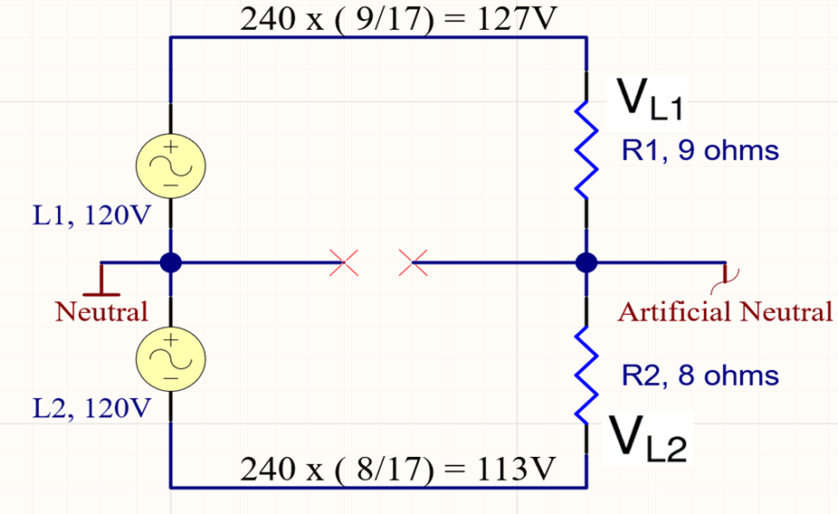
This is shown in Figure 1. Here we have 1600 W of load on leg 1, and 1800 W on leg 2. That loading is represented by 9 ohms and 8 ohms, respectively. The leg currents are 13.3 A and 15 A, with a neutral current of (L1-L2) = 1.7 A. With an open neutral, that 1.7 A cannot flow to the transformer. The voltage on L1 and L2 can be computed as 240 x (R1/(R1+R2)) = 240 x 9/(9+8) = 127 V, and 113 V. The artificial neutral is 7 Volts above the real neutral. One leg has increased by 7 V, and the other decreased by 7 V. A more severe difference in leg currents would cause a larger voltage shift.
Grounding
The situation changes when we take into account grounding. Almost all residential services will include a ground rod at the meter base. The neutral and ground are bonded at the service entrance (meter base). Additionally, the transformer center tap is likely grounded at the pole or transformer pad. These grounds provide a parallel path for current to flow from the service entrance to the transformer center tap – through the ground itself, as shown in Figure 2.
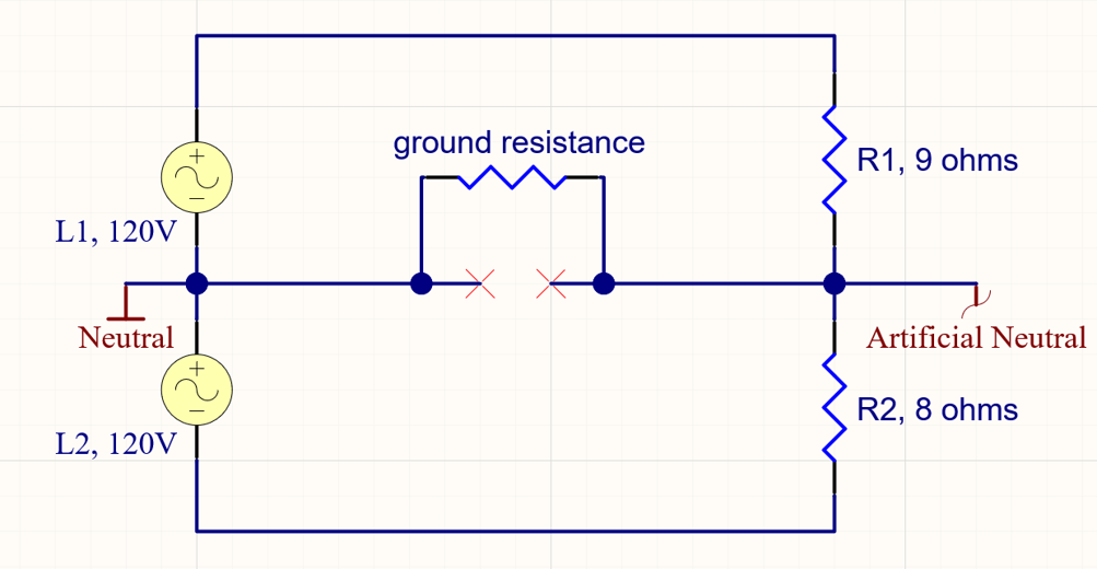
The electrical resistance through the ground varies widely with soil characteristics, ground rod depth, and distance from the transformer ground to the meter base. Typical ranges are single-digit ohms to hundreds of ohms. This resistance may also change with weather, especially rain or snow. As the ground resistance increases, the circuit approaches the limiting case of a complete open on the neutral.
Assuming a relatively low ground resistance of 10 ohms, the artificial neutral voltage changes from 7 Volts to approximately 5 Volts. This reduces the L1 and L2 shifts enough to stay just inside the ANSI C84 voltage regulation limits (114 and 126 V), and consequently less noticeable in general. Any higher ground resistance would push the voltage excursions higher, and in the limiting case an infinite resistance (a complete break) it is back to the original 7 Volts.
Keep in mind that the ground resistance effect depends completely on the size of the loads. In this example we have a 10 ohm ground resistance, and 9 and 8 ohms of load. The ground resistance is comparable in magnitude to the loads themselves. With a lightly loaded house, for example at night, the load resistances could be much higher. If the ground resistance is much lower than the loads, the ground functions more like a real neutral. If the ground resistance is much higher than the loads, the circuit approaches regular open neutral behavior.
In general, the ground path either has little effect, or tends to lower the open neutral voltage shifts, thus masking the root issue. The lower the ground resistance compared to the loads, the more masking occurs.
The ground current causes an additional, more serious problem than neutral masking. Because there is current flowing through the ground resistance, there is a voltage drop across it. This can cause a voltage to appear on grounded objects in the home. In the above example, 5 VAC on the ground might be enough to give a tingle or small shock to someone. In that example, a ground resistance of 10 ohms was assumed – this very much on the low side of the range. A more typical ground may be in the hundreds of ohms. With loads in the kilowatt range, that level of ground resistance is approximately an open neutral, placing nearly full artificial neutral voltage on local grounds. This can be enough voltage to produce a shock hazard to anyone in the home. In some cases, this symptom from customers may be the only symptom.
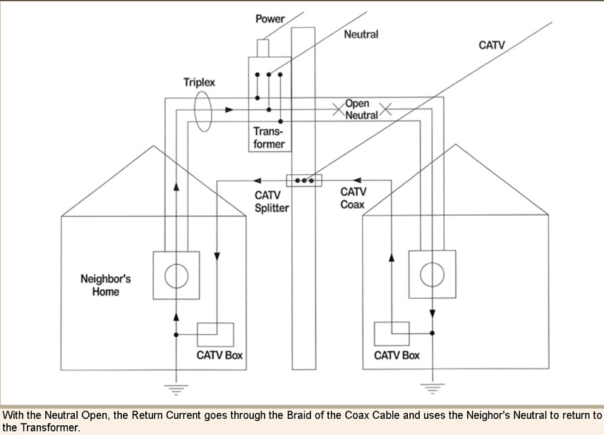
The ground situation may be even more complex if multiple homes are fed from the same transformer, and have other grounds in common, such as cable television or gas lines. For cable TV fed by coax, the coax ground braid is connected to earth ground somewhere close to the service entrance. Multiple houses on the same secondary will have a common ground path through the coax braid. If one home has an open neutral, current can flow through that home’s coax braid back to another house, where the coax is bonded to the neutral. That neutral then provides the path back to the transformer secondary, as shown in Figure 3 from https://www.electrical-forensics.com/Open-Neutral/Open-Neutral.html
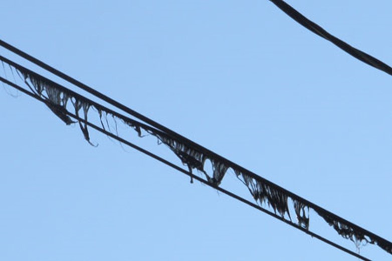
In this case, the full neutral current flowed through the coax braid. A typical RG-59 braid is about 1.1 ohms per 1000 feet, in between #10 and #12 AWG. This is certainly not rated for the neutral currents that may appear in a house; in this case the coax insulation melted due to the excessive heat (Figure 4). The coax may provide enough of a neutral to mask the open neutral condition until the coax itself fails. Measuring the current through coax with a clamp-on ammeter may reveal this situation.
Conclusion
The classic loose neutral symptom is the rise in one voltage leg paired with the same size fall in the other voltage leg. Customer symptoms include flickering lights, step increase in light brightness, and frequent UPS operations. Grounding complications may mask these symptoms, while introducing new ones. In particular, reports of getting a tingle or shock from grounded objects requires immediate attention and may be a symptom of the ground carrying neutral current while the neutral is intermittent or open. Always check the loose neutral graphs in any single-phase PQ investigation, but also keep in mind that ground current may mask the voltage shifts. A check of coax current, and ground voltage may help determine the presence of an open neutral.
