Abstract
A “flickering lights” customer complaint may be the first symptom of a dangerous loose/open neutral. Loose neutrals can cause high voltage equipment damage, and in extreme cases, excessive current flow can result in a fire. PMI recorders include a Loose Neutral Report to help identify possible loose neutral situations. This report is designed to work with one second average voltages, making it less sensitive to intermittent connections. A new graph template has been created for ProVision, specially designed to highlight the conditions that may indicate a loose neutral with single-cycle voltage values.
Characteristics of Loose Neutral
Loose neutrals are a common problem in single-phase residential services. In a single-phase service, two 120V legs are available. They are referenced to neutral and are 180 degrees out of phase, giving 240V between them. Any 120V load on either leg returns current through the neutral conductor. If the two 120V legs have exactly equal loads, the neutral return currents from each leg exactly cancel out, resulting in no neutral current. This is equivalent to a single 240V load across both legs, with no connection to the neutral at all. Otherwise, the neutral current is the difference in load current between the two legs.
In the example circuit of Figure 1, two loads are shown, one on each 120V leg. The computer is a 6 amp load; the light is 4 amps. The difference in current, 2 amps, would flow through the neutral (ignoring any difference in waveshape due to harmonics, etc.), and 120V would appear across the inputs of both loads.
If a break in the neutral occurs (shown with the X marks in the figure), then the current cannot flow through the neutral. In this case the loads are now in series with a 240V voltage source, and the current through each must be the same. The voltage across each load now depends on their individual impedances, and in this case (assuming for the sake of discussion that they’re linear loads), the computer would have 4/10th of the 240V, while the light would have 6/10th – putting 96V on the computer, and 144V on the light. The more unbalanced the loads, the lower the voltage on one leg, and the higher on the other. If the loads happen to be well balanced, the condition can persist without causing many symptoms, especially if the neutral isn’t completely open.

From above, the characteristic sign of the loose neutral is the voltage in one leg rising, the other falling, and the total of the two legs roughly equaling the original total. The Loose Neutral Report in ProVision is triggered by those conditions, but operates on one second RMS voltage readings. Thus, an intermittent neutral that changes quickly may be missed. Also, having loose neutral information in stripchart form allows for a continuous view of the trigger conditions during the recording, which can help in situations where the neutral isn’t yet degraded enough to trigger the report.
Graphing Loose Neutrals with ProVision
The new graph template, available for download here, is designed for single-phase situations. After importing into ProVision, the graph template will appear in the “Graphs and Reports” section of ProVision, labeled “2CH Loose Neutral” (see Figure 2). To draw the graph, open a ProVision file, and double click the graph template. An example is shown in Figure 3.

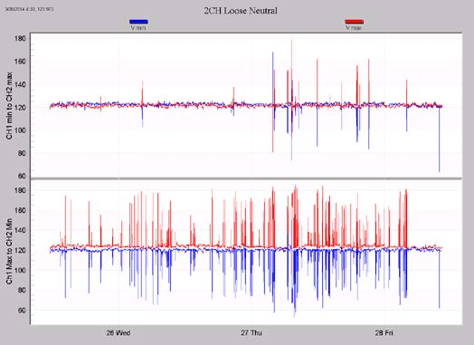
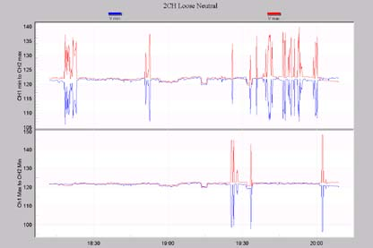
The graph is composed of two plots. In the top plot, the channel 1 minimum voltage is plotted, along with the channel 2 maximum voltage. In the bottom plot, the min/maxes are reversed – channel 1 maximum is plotted with the channel 2 minimum. These are all one cycle min/max values – the stripchart average voltage is not plotted. In both cases, the minimum is in blue, and maximum is in red. Since the characteristic of a loose neutral is that one leg rises while one leg falls, the max and mins from opposite legs are plotted together. Which specific leg rises, and which falls depends on the actual load balance at that time, and can change from moment to moment. In a loose neutral situation there will likely be a large separation between the max and min values, but that separation could appear in either plot. This graph shows several instances of separation in the bottom plot; one is circled in orange.
If the loose neutral lasts for longer than the stripchart interval, then the separation would affect both the individual max and min for each channel, and in that case the separation would appear in both plots at the same time. If the condition doesn’t last for the entire interval, the separation only appears in one plot. In the example from Figure 1, before the open neutral, the min, max (and average) for L1 and L2 would all be 120V. During the open neutral, L1 would go to 96V, and L2 to 144V. If this lasted for just a few cycles in a single stripchart interval, the min for L1 would be 96V, but the max would still be 120V, and for L2, the min would be 120V, and the max 144V. If the open neutral persisted for an entire stripchart interval, the min and max for L1 would be 96V, and the min and max for L2 would be 144V, and the signs would appear in both plots. Thus, we can judge how intermittent the condition is by seeing if the separation appears in both plots, or just one.
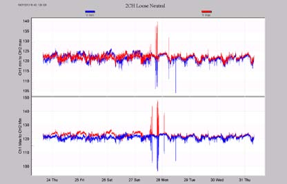
Zooming out to the entire recording session (Figure 4), we see many possible loose neutral excursions in the bottom plot, and some in both.
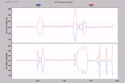
Zooming in to an area where both plots show excursions (Figure 5), there are times when both plots show problems, and periods of sustained loose neutral conditions.
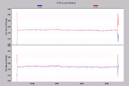
A second example is shown in Figure 6. Here there are sustained excursions (as seen by their presence in the top and bottom plot), but just at the very start and end of the recording. This could possibly indicate an intermittent connection that was brought to visibility by the meter technician physically handling the meter base during installation and removal.
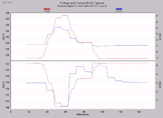
A third example is shown in Figure 7 (entire recording graphed), and Figure 8 (zoomed in). The condition doesn’t appear in a sustained fashion, and the Loose Neutral Report was not triggered. A typical waveform from this recording is shown in Figure 9, graphed as an RMS capture (where a sliding RMS window is applied to the raw waveforms). Channel 1 rises to 137V, and channel 2 falls to 108V, but the condition only lasts for around 3 cycles – not enough to affect the one second average voltage.
The graph template only requires RMS voltage stripcharts to be recorded. Since all PMI recorders have one cycle RMS resolution on the min and max readings, regardless of the stripchart interval, just about any single phase recording has the required data to generate the loose neutral graph. Any existing file may be analyzed with the new template, as well as new files.
Note that the separation of the voltage legs can be indicative of the presence of a loose or open neutral, but is not conclusive. More importantly, even if no separation of the voltage legs is seen, a loose or open neutral may exist – it cannot be concluded that a loose neutral doesn’t exist if the graph looks good. Well balanced loads, returns through a ground, etc. can mask the symptoms of a loose neutral in the recording.
Conclusion
A new graph template is available for ProVision specifically for loose neutral investigations. By graphing two channels’ min and max values together, the characteristic signature of a loose/open neutral condition is made as visible as possible, with one cycle resolution.
