Abstract
In this white paper I define linear and non-linear loads, describe what characteristics cause a load to be linear or nonlinear, and show how these load types can affect the distribution system and power quality.
“Linear load” refers to a load that presents a single, constant impedance to the source, regardless of frequency. More rigorously and generally, a linear system obeys the property of superposition: if one or more inputs are varied by a certain proportion, the system output varies by the same proportions, on an instantaneous basis. Any load that doesn’t produce a direct, proportional response to a change in voltage is nonlinear. In practice, any load that can’t be modeled by a combination of resistors, capacitors, and inductors is a nonlinear load.
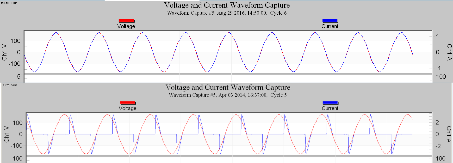
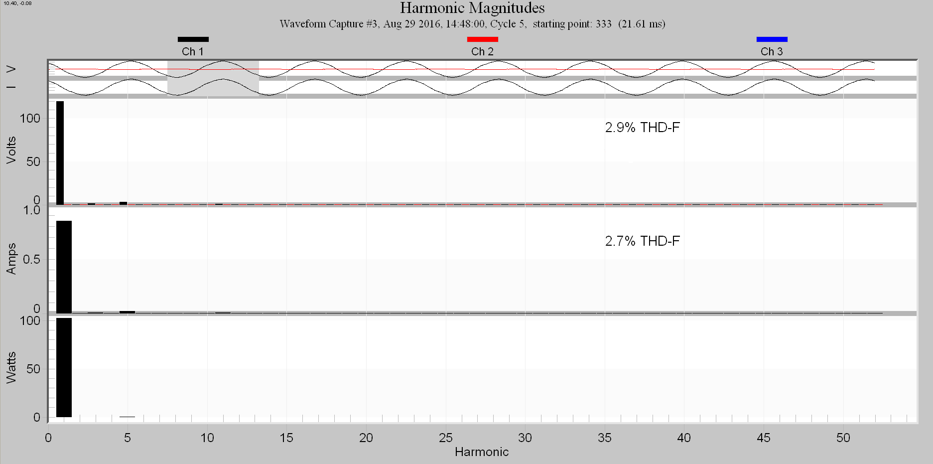
The constant impedance (with time) allows the wave shape of the steady-state current to follow the wave shape of the applied voltage (excepting a phase shift). Linear loads can be resistive, capacitive, or inductive, but the impedance must remain fixed throughout the full power cycle. A linear load does not change its impedance even if the source’s output changes. With this linear relationship, the source’s voltage waveform, whatever it is, will not be distorted in shape by the linear load. A sine wave voltage source applied to a linear load will result in a sine wave current at the same frequency, with no other distortion or waveform changes. The voltage waveform’s amplitude and phase angle may change, but it will remain a pure sine wave of the original frequency. Similarly, if the voltage waveform is already distorted with the addition of harmonics, the current from a linear load will also have each of those harmonics present, with no additional harmonics added. Each current harmonic may be shifted in phase from the voltage but no other frequencies will be added.
For a purely resistive load, it’s easy to visualize why it’s linear, but for a capacitive or inductive load, it’s not quite as obvious. Capacitors or inductors, as long as the dynamic range of the components is not exceeded, do present a constant impedance at a given power line frequency (e.g. 60 Hz). For example, with a capacitor, the capacitive reactance or impedance in Ohms is equal to one divided by two times pi times the frequency in Hertz times the capacitance in Farads, or Xc=1/(2πFC). This impedance does not change with source voltage fluctuations so the impedance remains constant and the load remains linear. In the frequency domain, each possible harmonic component of the voltage will see a fixed impedance as per the reactance formula above, which results in a proportional relationship between voltage and current at each frequency. No new frequency components can be created with this simple relationship, making the load linear.
An inductor, as long as the core does not become saturated, also presents a constant load at each frequency. At the point in which the inductor’s core becomes saturated, it will become non-linear and therefore so will its load. This implies that inductors present linear loads only within certain limits. An inductor that is not saturated presents an impedance in Ohms equal to two pi times the frequency in Hertz times the inductance in Henries or Xl = 2πFL.
Non-linear loads present a change in impedance vs time to the voltage applied to the load. This impedance change can be very abrupt, thus causing an abrupt change in the current waveform. This interaction causes the waveform to become distorted. There are three basic groups of non-linear: the electronic group containing semiconductors, the ferromagnetic group containing transformers and motors, and the arcing group such as arc furnaces or lighting. Non-linear loads produce harmonic currents and thus are causes of harmonic voltage distortion.
Examples of some straightforward linear loads are resistive heaters and incandescent lights. Both are resistive load and present a constant load to the source; the source’s waveform shape is not changed. Linear loads, as mentioned before, do not have to be totally resistive. They can also have capacitive or inductive elements, as long as their impedance does not change with time within the power line cycle. Power factor correction capacitors are one example of a purely non-resistive linear load. These capacitors shift the current waveform phase and provide the voltage source with constant impedance, thus not changing the waveform’s shape. Motors and transformers are the traditional inductive counterparts, although motors also have a resistive component corresponding to the mechanical power delivered and resistive losses in the motor.
Some examples of non-linear circuit elements from the semiconductor group are diodes or rectifiers, transistors, SCR, and thyristors. Also, devices that incorporate these circuit elements such as switching power supplies, variable frequency drives, or electronic power converters usually present non-linear loads.
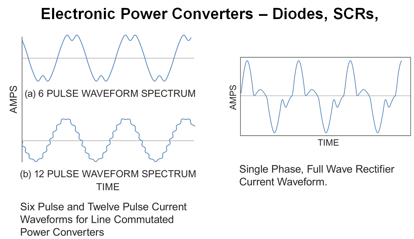
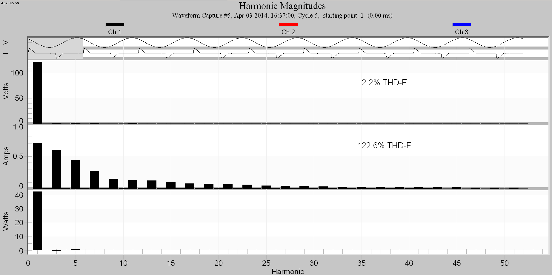
Power semiconductors are often used as switches (e.g. transistors, IGBT, etc.) or for rectifying AC into DC (diodes). These operations are very non-linear, with abrupt impedance changes from near zero (closed circuit) to near infinity (open circuit). As an example, rectifiers are used to convert AC into DC. In this process, an AC sine wave is applied to the input of a diode rectifier. As the sine wave progresses from zero volts, there is a point where the sine wave’s positive voltage exceeds that of the diode’s P-N junction’s internal barrier potential, causing the diode to abruptly start conducting. For typical silicon type diode rectifiers, this occurs around 0.65 to 0.7 volts. At this point, the forward current increases abruptly for a very small increase in voltage, which produces a non-linear curve. The diodes will continue to conduct during the positive portion of the sine wave until the positive voltage drops below the diode’s internal barrier potential to the point where the diode is then reversed biased and the cathode becomes positive with respect to the diode’s anode. At this point in the cycle, the diode abruptly blocks the current except for a small amount of leakage current. The diode will continue to block the current flow until the voltage becomes positive again and then the cycle repeats. This behavior of a diode is one example of a non-linear load. The change in the load impedance during the cycle changes or distorts the waveshape of the current. This distorted current contains new frequencies that may not have been present in the voltage waveform. The current results in distorted voltage drop throughout the distribution system, presenting distorted voltage to other customers.
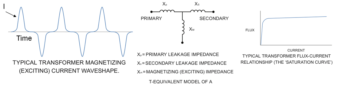
When the magnetic core of a power transformer or motor winding becomes saturated, the load it presents to the source becomes non-linear. This occurs when the amplitude of the voltage, creating the magnetic flux, is large enough to enter into the nonlinear region of the B-H curve, as seen in Figure 5. At this point, the magnetizing current that is required will cause distortions in the sine wave. The major effect on power quality, as with most non-linear loads, is harmonics.
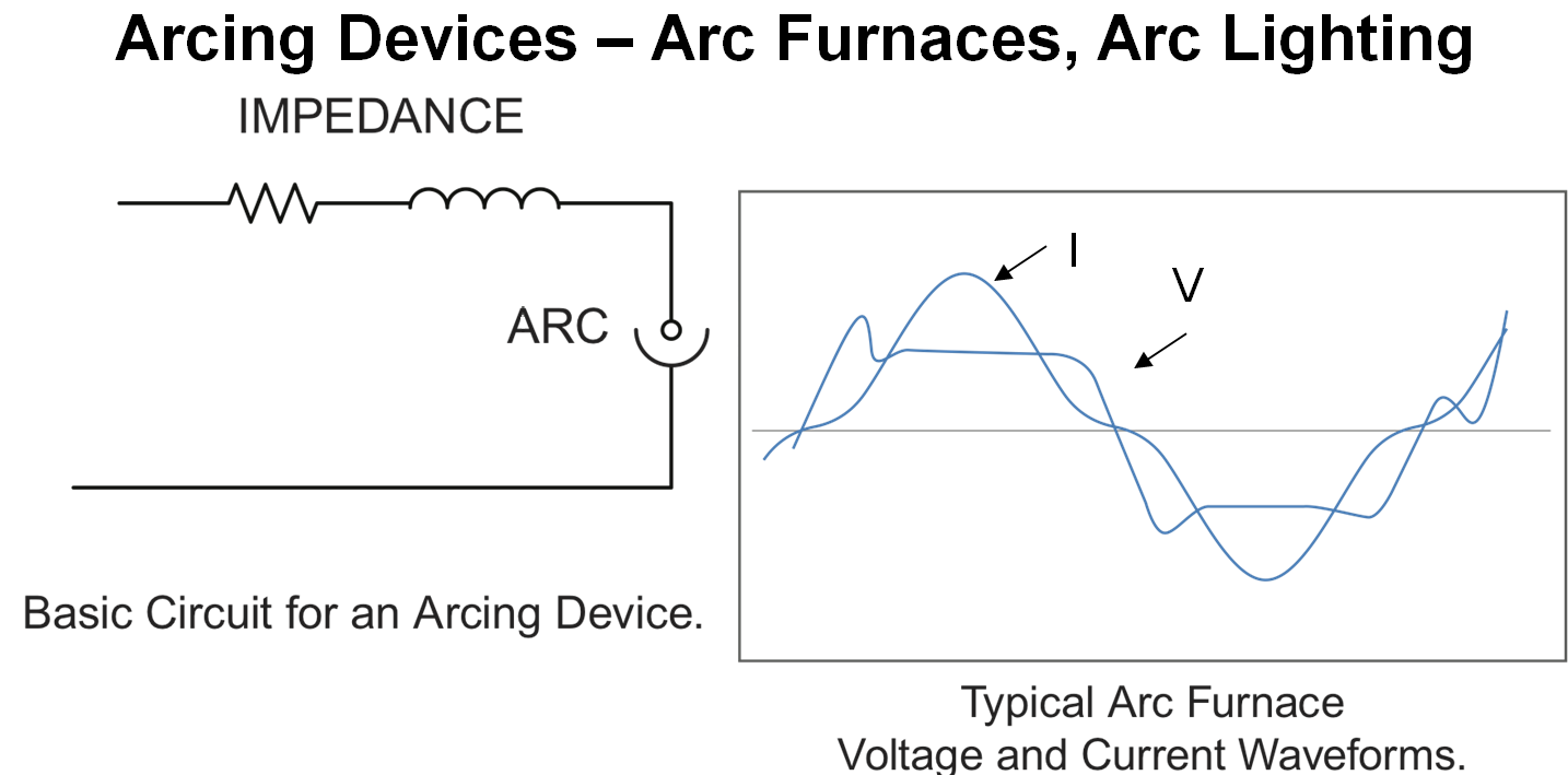
The reason an arc device such as an arc furnace is considered a non-linear load is because of its three operational states that have unique circuit impedances during its operational cycle. The three states are: open circuit state; as the voltage builds up before the ions are not rich enough to support conduction, the shorted circuit state; when the arc occurs during conduction, and then the normal circuit state. In Figure 6, the distortions in the voltage and current waveform clearly show how the changes in impedances within a 60 Hz cycle change the waveform. As for power quality, arc furnaces are usually operated near to maximum arc power which corresponds to a power factor of 70%.
Due to extreme impedances changes, from open to short, and arc furnace’s huge power requirement, these tend to be one of the worst sources of fluctuations in a power system. It is very common to have objectionable light flicker during arc furnaces operation, in addition to the harmonic distortion.
Summary
A linear load refers to a load that presents constant impedance to the source. A linear load follows Ohm’s law and does not generate new frequencies or harmonics. A linear load can be resistive, capacitive, or inductive. Examples of a linear load are resistive heaters, incandescent lights, or power factor correction capacitors. If the incoming voltage already contains harmonic components, a linear load’s current will contain these same harmonics, and no others (although their amplitudes and phases may vary).
A non-linear load refers to a load whose impedance changes with changes to the applied voltage, especially on an instantaneous basis. Non-linear loads can be very problematic to power quality and power distribution systems. Non-linear loads change the wave shape of the applied voltages and cause the generation of new frequencies (e.g. harmonics), that can cause the distribution system to degrade by overheating critical components such as transformers and wiring.
