Abstract
Temporary overvoltage is a common, but often overlooked stress condition on modern electric distribution systems. Although it receives less attention than lightning and fast transients, it can damage equipment, overheat surge arresters, and distort voltage waveforms long enough to trip protective devices or trigger customer complaints. A sound grasp of temporary overvoltage mechanisms supports better design decisions, protection coordination, power quality monitoring, and claims evaluation.
This paper concentrates on power-frequency overvoltages that last from a few cycles to several hours. The emphasis is on distribution-level phenomena that occur between the substation low-voltage bus and the customer service entrance. Grounding practices, switching procedures, and equipment configuration largely determine the severity of each event. Intended readers are utility power quality, protection, and reliability engineers who need practical guidance that connects field signatures with root causes and credible magnitude–duration ranges.
Working Definitions and Measurement
Temporary overvoltage is an abnormally elevated voltage at power frequency that persists longer than a transient yet remains temporary in nature. In practice, engineers treat an event as a temporary overvoltage when one or more conductors exceed nominal by about ten percent or more for long enough to stress insulation, heating elements, or surge-protective devices. A common trigger for monitoring is 1.10 per unit. That threshold corresponds to 110 percent of nominal and is typically sustained for several cycles or longer.
Classification relies on two parameters. The first is magnitude, which is the ratio of measured voltage to nominal and is expressed in per unit (pu) terms. The second is duration, which is the time the voltage remains above the selected threshold. Considering both parameters helps distinguish brief switching artifacts from sustained control errors and from fault-driven events with distinct clearing behavior.
Temporary overvoltage is related to, but different from, other voltage phenomena. A swell is a moderate rise in RMS voltage that usually lasts less than one minute and often follows capacitor switching or load rejection. An impulsive transient is a short-duration, high-frequency event caused by lightning or switching. Temporary overvoltage lasts longer and is linked to network grounding, topology, and operation. Ferroresonance is a frequent subtype in which resonance sustains an overvoltage for seconds or minutes.
Measurements should support both detection and diagnosis. Engineers monitor line-to-line and line-to-neutral voltage, since unfaulted or open phases in distribution networks often experience the largest rise during faults or switching. Per-unit normalization is helpful across voltage classes.
Power quality recorders benefit from high sampling rates and should capture RMS envelopes that span from seconds to hours. Many utilities set detection at about 1.10 per unit with hysteresis to avoid chatter. Recording phase-to-ground and phase-to-phase channels is valuable, and adding neutral-to-ground voltage often reveals open-neutral or grounding problems. When control malfunctions are suspected, correlating voltage data with regulator tap positions and capacitor controller states improves root-cause analysis.
Why Temporary Overvoltage Matters for Utilities
Temporary overvoltage exposes weaknesses in grounding, protection coordination, and asset robustness. Arresters are designed to absorb brief surges, not to conduct at power frequency for extended periods. During a temporary overvoltage, they may conduct for seconds or minutes, which increases temperature and can lead to thermal runaway and failure. Transformers can enter core saturation, which raises magnetizing current and causes localized heating. That condition may degrade insulation or operate upstream protection. Recloser controls, potential transformers, and voltage regulators can experience premature wear when exposed to repetitive or prolonged elevation.
Customers experience these events as bright lighting, nuisance trips, or outright appliance failures. Open-neutral and ferroresonant conditions are notable for damaging electronics or overheating point-of-use surge strips. These cases frequently lead to claims, sometimes even when the cause is within the customer’s own service or wiring. Utilities that maintain voltage logs through power quality recorders or advanced metering can correlate measured excursions with complaint timing. That capability supports claims resolution and indicates where grounding, service connections, or control devices require attention.
Temporary overvoltage often accompanies reliability events such as ground faults, regulator misoperations, or switching. If clearing times are extended, elevated voltages can overlap reclosing intervals or influence relays that rely on voltage magnitude. Repeated exposure weakens arresters and reduces insulation margins. In rare but serious cases, such as a contact between transmission and distribution circuits, overvoltage can propagate across a feeder and cause widespread arrester stress and multiple customer impacts. Recognizing these dynamics allows engineers to specify devices that remain within safe thermal limits for credible events.
Timely recognition turns reaction into prevention. Distinct voltage signatures reveal faults, open neutrals, or ferroresonance and point to the correct corrective action. Incorporating temporary overvoltage awareness into grounding verification, modeling, and controller commissioning reduces exposure and improves reliability.
Fault-Induced Neutral Shift
A single line-to-ground fault shifts the local ground reference. The faulted phase collapses toward zero, while unfaulted phases rise in line-to-ground voltage. The magnitude depends on the effectiveness of grounding along the circuit and at the substation. Four-wire multigrounded systems tend to limit the rise through parallel ground paths and low earth impedance. Sparse or high-impedance grounding produces larger shifts. Double line-to-ground faults can also elevate the unfaulted phase, although single line-to-ground faults are more common in operations.
Typical unfaulted-phase voltages in distribution systems are about 1.2 to 1.3 per unit. Values near 1.5 per unit can occur where grounding continuity is poor. Duration is tied to clearing and is commonly between a tenth of a second and two seconds. Longer exposure can occur when protection coordination is slow or when high-impedance faults delay fuse operation. On feeders with reclosing, repeated operations may produce multiple short exposures that accumulate arrester heating.
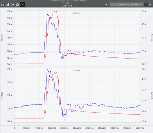
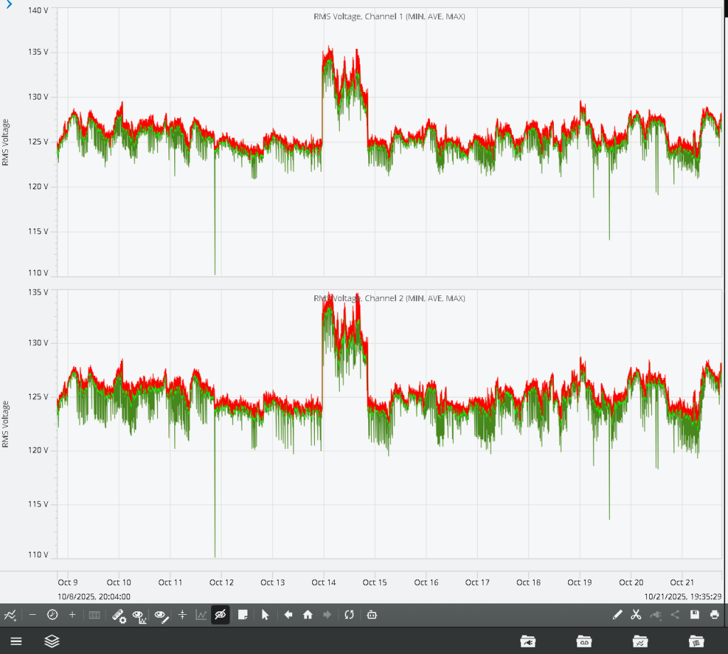
Power quality records show a sharp drop on the faulted phase at the same time as a step increase on the unfaulted phases. Figures 1 and 2 show examples of recloser-related temporary overvoltage events captured during fault clearing and reclosing.
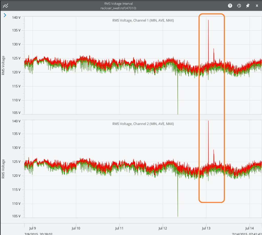
Figure 1. Single-phase fault-caused TOV in stripchart
The rise ends when protection clears or recloses. Waveforms may show distortion from transformer saturation. Customers on unfaulted legs sometimes report bright lighting or equipment trips even when the fault is remote from the service.
Severity depends on several factors. High grounding density restricts the rise. Lower fault resistance deepens the ground potential shift. Modern metal-oxide arresters begin to conduct near one and a half per unit in a line-to-ground reference, which moderates peaks but introduces thermal risk if clearing is delayed. Circuit topology matters as well. Long laterals and ungrounded delta sections increase displacement.
Open Secondary Neutral
A loose, open or high-impedance neutral on a 120/240-volt service is a frequent and damaging source of overvoltage inside premises. The problem appears when the neutral conductor between the transformer and the service entrance is corroded, mechanically damaged, or loosely terminated. Figure 3 shows an example of a temporary overvoltage caused by an open secondary neutral.
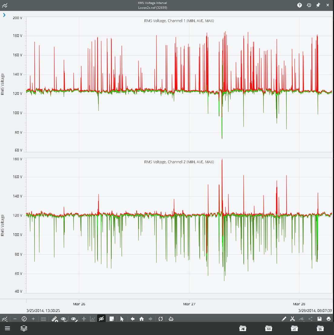
Because the two 120-volt legs share a common neutral, the loss of that path allows the neutral point to float. The floating point behaves like a divider set by the relative impedances of the loads on each leg. The heavily loaded leg sags, and the lightly loaded leg rises. The leg voltage can range from near zero to nearly 240 volts.
In practice, the elevated leg often reaches 1.3 to 1.5 per unit. Under severe imbalance it can approach 2.0 per unit, which is about 240 volts on a 120-volt base. Since an open neutral is a condition rather than a momentary disturbance, exposure commonly lasts hours and can persist for days until the utility locates and repairs the connection. Severity varies with customer behavior, because load changes on each leg move the neutral point.
The condition has recognizable signs. Lighting on one side of the panel appears unusually bright while the other side dims. Damage clusters on one branch circuit. Voltage fluctuates with the operation of motors or heaters. The voltage stripchart traces show one 120-volt leg well above nominal while the other sags, with line-to-line voltage near 240 volts. On shared secondaries, the floating potential can migrate among services depending on each premise’s grounding quality.
Severity is governed by the integrity of grounding and the distribution of load. Strong neutral-to-earth bonds at the service and transformer partially stabilize the floating point, although they do not remove the hazard. High soil and pole-ground impedance allows larger unbalance. A fully open conductor produces the largest effect. Corroded or intermittent neutrals create voltage swings that track load cycles.
An open neutral is both a power quality issue and a safety hazard. Elevated leg voltage overheats appliances and can destroy surge protectors. The neutral conductor or bonded metallic parts may rise above earth potential.
Ferroresonance
Ferroresonance arises when a transformer’s magnetic characteristics interact with circuit capacitance to form resonance at or near power frequency. Normal balanced operation is stable. When one or two phases open during single-phasing, switching, or fuse operation, the balance is disturbed and the transformer can enter a nonlinear oscillation that drives voltage well above normal. The condition is most associated with cable-fed banks that have significant line-to-ground capacitance, lightly loaded or unloaded transformers, and ungrounded or floating-wye primary connections.
Certain switching sequences energize only one or two phases for an interval, which is often enough to initiate the resonance. The effect usually sustains until the circuit is fully energized, fully de-energized, or a resistive load is applied. Figure 4 illustrates a ferroresonant overvoltage event captured during single-phase switching of an unloaded transformer.
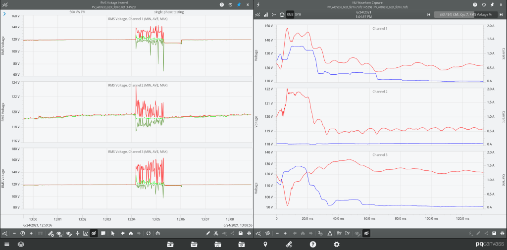
Electrically, ferroresonance is a nonlinear process marked by alternating core saturation and energy exchange with capacitance. As the core saturates, it permits rapid energy transfer. As it desaturates, trapped charge reverses polarity. The cycle repeats every half period and produces distorted and sometimes chaotic oscillations. Field measurements commonly show 1.5 to 2.0 per unit. Severe ungrounded cases have reached 3 to 5 per unit. Duration ranges from seconds to several minutes and depends on load and switching sequence.
Typical records include distorted voltage waveforms with half-cycle irregularity, elevated line-to-ground voltage on open phases, and audible transformer noise even with little or no load. Arresters or fuses may operate after switching of unloaded transformers. Spectral analysis shows strong harmonic content near the fundamental, which separates ferroresonance from lightning or high-frequency transients.
Severity reflects several design and operating parameters. Floating-wye and delta primaries are most prone. Grounded-wye units are less susceptible, but designs with a common magnetic core, such as five-legged construction, permit phase coupling that can still sustain resonance. Longer underground cables and shielded conductors increase capacitance to ground.
A small resistive load can damp oscillations and prevent onset. Modern low-loss steels and amorphous cores reduce inherent damping and increase likelihood. Higher system voltages raise reactive energy for the same capacitance and increase potential peaks.
Consequences include heavy arrester conduction with attendant thermal risk, transformer heating from saturation and magnetizing current, and elevated secondary voltages that reach customer equipment. Many events clear when switching completes or load changes, yet severe cases can destroy arresters or damage winding insulation.
Poor Voltage Regulation and Control Errors
Voltage control devices can create temporary overvoltage when they malfunction or lose coordination. This category includes voltage regulators, load-tap changers, and capacitor-bank controllers.
The result is usually a moderate overvoltage that persists for minutes or hours rather than a short event associated with faults or impulses. These problems arise at substations and along feeders with intermediate devices. Common initiators include:
- Mis-set targets and bandwidths
- Controller failures such as stuck tap changers or faulty sensors
- Incorrect time clocks on capacitor controllers that energize at light load
- Sudden load loss downstream of a regulator that leaves the output high until tap control responds
Magnitudes are typically around 1.10 to 1.15 per unit and can reach 1.20 per unit in adverse cases. Duration often extends until a controller readjusts or maintenance restores normal operation. On long or lightly loaded feeders, multiple misaligned devices can create localized zones of sustained high voltage across several customers.
Periodic oscillations sometimes appear and align with capacitor switching or tap movement. Customer reports of bright lights, early lamp failures, or overheating of heating elements cluster in the affected area. Post-event review often finds a regulator or capacitor bank in an energized or overcompensated state. Figure 5 presents an example of a sustained temporary over-voltage resulting from regulator misoperation.
Root causes include unsynchronized controllers, incorrect line-drop compensation, sensor drift or miscalibrated tap position feedback, regulator hunting from tight bandwidths and fast response, bidirectional or cogen regulation issues, and simple human error during seasonal adjustments. Although magnitudes are modest, the long duration increases thermal stress on distribution transformers, shortens arrester life, and reduces the longevity of electronic equipment.
Magnitude–Duration Windows and Relative Risk
Temporary overvoltage exposure depends on how high the voltage rises and how long it remains elevated. Short, high-magnitude events test insulation margins and arrester coordination. Long, moderate events cause cumulative heating and component aging. Most distribution events fall into recognizable windows. Fault-induced neutral shift typically produces about 1.2 to 1.3 per unit and can approach 1.5 per unit, with exposure commonly between a tenth of a second and two seconds. An open secondary neutral often yields 1.3 to 1.5 per unit on the elevated leg and can reach about 2.0 per unit under extreme imbalance. Exposure commonly lasts hours. Poor regulation produces about 1.10 to 1.15 per unit and can reach 1.20 per unit, with durations measured in hours. Ferroresonance often produces 1.5 to 2.0 per unit and can reach about 3.0 per unit in severe cases, with durations of seconds to minutes.
Risk varies by mechanism. Open neutrals and regulation errors are frequent and prolonged. They affect modest geographic areas yet remain the leading sources of customer claims because exposure lasts long enough to damage appliances and electronics. Fault-induced rise occurs daily somewhere on a typical network. It is usually short and more threatening to arresters and transformer insulation than to end-use devices. Ferroresonance is uncommon but destructive. It can produce arrester failures and transformer damage and deserves attention in risk assessments and switching.
Conclusion
Temporary overvoltage is an umbrella term for several distinct mechanisms, each with its own causes, signatures, and risks. Across these mechanisms, modest elevation combined with sufficient duration creates significant thermal and electrical stress. On distribution systems, the most consequential contributors are fault-induced neutral shifts, open secondary neutrals, control malfunctions, and ferroresonance. Fault-related cases are brief and widespread. Open-neutral and regulator problems develop slowly and can persist for hours. Ferroresonance is less frequent but highly unpredictable and potentially severe.
Understanding these behaviors improves diagnosis, supports fair and accurate claims handling, and guides reliability planning. Recognizing signatures in monitoring data helps engineers trace causes, confirm grounding and control performance, and identify places where protection margins are thin. While complete elimination is unrealistic, consistent grounding integrity, careful switching, and disciplined control verification limit impact. Structured monitoring and analytics reveal patterns early and support targeted intervention.
