
Abstract
Ferroresonance is a nonlinear electrical phenomenon that can damage transformers, surge arresters, cable insulation, and switchgear — and create dangerous backfeed voltages on conductors that should be de-energized. Although relatively rare, the conditions that make ferroresonance possible are becoming more common as utilities install more underground cable, adopt high-efficiency low-loss transformers, and interconnect distributed generation. This paper provides a practical overview of ferroresonance for distribution engineers and field crews: what causes it, how to recognize it, what it does to equipment, and how to reduce the odds of occurrence through proper switching practices and system design.
What Is Ferroresonance?
Ferroresonance is an abnormal oscillation that occurs when a transformer’s nonlinear magnetizing inductance interacts with system capacitance in a series circuit, under lightly loaded or unloaded conditions. The word itself, from the Latin ferrum for iron, reflects the fact that the iron core of the transformer is central to the problem. Resonance involving transformers was first reported in 1907, and the term “ferroresonance” was coined in 1920.
In a normal LC resonant circuit, the inductance is constant and behavior is predictable. A single resonant frequency can be calculated, and standard engineering tools work well. Ferroresonance is fundamentally different because the transformer core’s inductance is not constant: it changes with voltage. As voltage rises, the core saturates and inductance drops. This creates a feedback loop: voltage changes cause inductance changes, which shift the resonant frequency, which changes the voltage. This feedback can sustain oscillations that produce voltages far exceeding the source, distort waveforms into subharmonic or chaotic patterns, and behave differently each time the same switching sequence is repeated.
Three ingredients must be present simultaneously for ferroresonance to occur:
- Nonlinear inductance — an iron-core transformer whose inductance changes as the core saturates.
- Capacitance in series with that inductance — most often from underground cable, but also from capacitor banks, internal transformer capacitance, or other sources.
- Light or no load — below roughly 10–20% of rated load, there is not enough resistance in the circuit to dampen the oscillation.
A triggering event, usually single-phase switching or an open-phase condition, completes the setup. Remove any one of these ingredients and ferroresonance cannot occur.
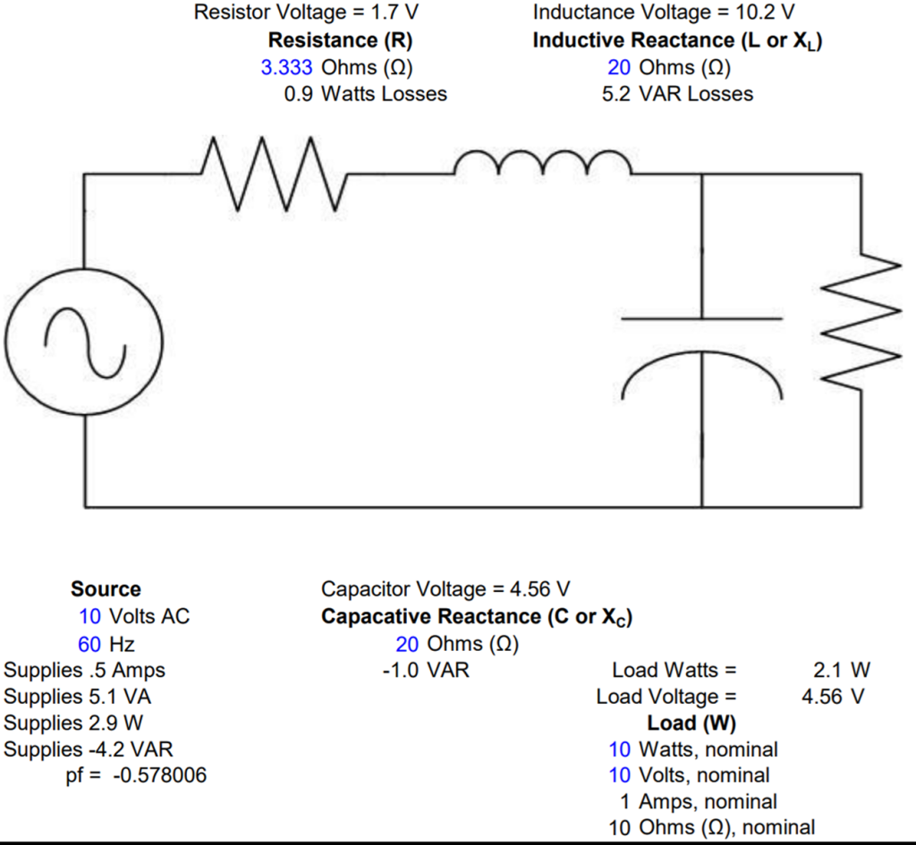
A simple numerical example illustrates why series resonance is dangerous. Consider a 10V AC source driving a series RLC circuit where the inductive reactance (20 Ω) and capacitive reactance (20 Ω) are equal, with only 3.33 Ω of resistance. Because the reactive impedances cancel, the current is limited only by the small resistance — and the voltage developed across both the inductor and capacitor reaches 60V, six times the source voltage. If the components were rated for only 10V, everything in the circuit fails — capacitor, inductor, and any surge arresters. The same physics applies at distribution voltages, just scaled up.
The practical corollary is equally important: adding even a small resistive load dramatically changes the outcome. In the same circuit, a 10-watt load reduces the inductor voltage from 60V to about 10V — an 83% reduction (Figure 1). This is why load is the single most effective defense against ferroresonance, and why the phenomenon overwhelmingly occurs during unloaded conditions such as new construction energization or planned maintenance.
Where Does the Capacitance Come From?
On distribution systems, underground cable is the primary source of capacitance. Longer cable runs and higher voltage ratings both increase the capacitance per foot. This is why ferroresonance has historically been associated with padmount transformers fed by underground laterals — the cable provides the “C” in the series L-C circuit.
But cable is not the only source. Power factor correction capacitor banks can create the same conditions, especially when installed downstream of single-pole fusing or switching devices. In that configuration, a blown fuse or open switch can place the cap bank in series with a transformer through the remaining energized phases — effectively the same circuit as a long underground cable.
Less obvious sources include capacitive coupling in double-circuit lines, breaker grading capacitors, generator surge capacitors, and internal transformer capacitance (winding-to-winding, winding-to-ground, and bushing capacitance). In one case, a bank of amorphous-core transformers resonated with their own internal capacitance. In this situation no external cable was needed at all.
A key concept is the “open-phase trick.” A shunt capacitor bank or cable capacitance is normally in parallel with the transformer. When one phase opens, that capacitance can be fed through the transformer windings from the remaining energized phases, converting a parallel connection into a series one. This is why overhead systems with cap banks downstream of single-pole fusing are also at risk — not just underground systems.
General industry guidance suggests keeping the last underground cable segment feeding a lone three-phase padmount as short as practical, with maximum lengths that decrease as system voltage increases and transformer size decreases. These guidelines are approximate and vary by cable type and installation — they reduce susceptibility but do not guarantee trouble-free operation.
Recognizing Ferroresonance
Ferroresonance can present through audible, visible, and measured indicators, often in combination. The progression typically follows a pattern:
- Mild: A louder-than-normal transformer hum, sometimes described as a rumble or growl. This may self-resolve when the remaining phases are connected.
- Moderate: Pronounced growling sounds and noticeable vibration. Crews should proceed with caution and close remaining phases quickly.
- Severe: Loud humming, visible transformer vibration, the unit physically moving on its pad, smoke, oil venting, blown surge arresters, or blown fuses.
In severe cases, the crew should stop immediately and de-energize the transformer.
From a measurement standpoint, ferroresonance produces distinctive electrical signatures. RMS voltage values become unstable, with large spreads between minimum, maximum, and average readings (Figure 2). Waveforms become visibly distorted — losing the clean 60 Hz sinusoidal shape and potentially dropping to subharmonic frequencies (30 Hz, 20 Hz, or even lower) or becoming chaotic and nonperiodic (Figure 3). Normal phase angle relationships break down, and voltage may appear on a phase that should be de-energized.
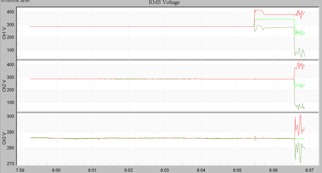
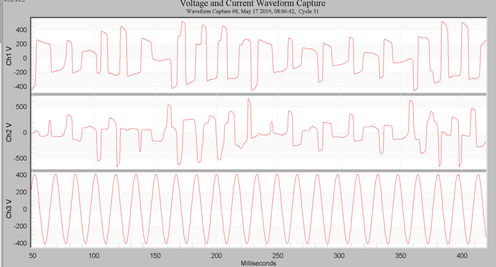
The field clue is the combination: if the transformer sounds wrong, the voltage readings are unstable, and the phase relationships no longer make sense, ferroresonance should be treated as a live possibility until proven otherwise.
It is worth noting that because ferroresonance is a nonlinear phenomenon, the same switching sequence can produce different results on different occasions. The outcome depends on switching angle, residual core flux, cable pre-charging, and other factors that vary from one operation to the next. Standard linear calculations will not predict it, and trending or extrapolating from one event to the next is unreliable.
Equipment Impacts
The damage from ferroresonance stems from two mechanisms: sustained overvoltage and excessive core flux.
High voltages — potentially 4 to 6 times nominal — can cause surge arrester failures (often the first component to go, and sometimes violent), transformer core-coil insulation breakdown, bushing flashover, and cable insulation failure. In cases where a cable fault is cleared by a fuse but ferroresonant backfeed voltage persists, “burn-back” of the cable insulation from the fault location toward the transformer has been observed.
High core flux from sustained over-excitation causes overheating, magnetostriction-induced vibration (which can be severe enough to break inflexible connectors or physically displace a transformer on its pad), and in extreme cases, structural damage to the core itself. Phase coupling during ferroresonance can also produce apparent secondary phase reversal, causing three-phase motors to attempt to run backwards. If metering or customer equipment is connected but unloaded, secondary overvoltages can damage that equipment as well.
In one documented case, a 112 kVA delta-primary padmount fed by 785 feet of underground cable experienced arrester failure within approximately 10 seconds of single-phase energization from a riser pole. The ferroresonant overvoltage developed through the delta winding to the un-energized phase’s cable capacitance, degrading the arrester before the second phase was even closed. In another case, a 2500 kVA transformer was destroyed when it was energized into 835 feet of cable with the downstream load switch still open — the cable’s shunt capacitance formed a resonant circuit with the transformer’s reactance.
Transformer Design and Susceptibility
Not all transformers are equally susceptible. The primary winding configuration has a significant effect: delta-connected primaries have the highest theoretical risk because of direct electrical coupling between phases through the winding. Ungrounded or floating wye connections are also susceptible. Grounded-wye primaries are less susceptible because the grounding shorts out much of the inter-phase magnetic coupling — but they are not immune, particularly with certain core designs.
Core construction determines how much magnetic coupling exists between phases (Figure 4). The five-legged wound core — the most common design in padmount transformers — will always produce roughly 50% backfeed voltage on an unenergized phase when an adjacent phase is energized, due to magnetic flux paths through the shared core legs. The three-legged core form design has even stronger inter-phase coupling, potentially producing up to 100% backfeed voltage. Only the triplex design (three electrically and magnetically separate single-phase cores in one tank) eliminates the inter-phase magnetic path entirely, making it the most ferroresonance-resistant design available.
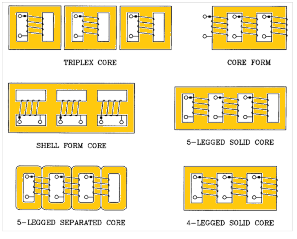
The trend toward low-loss transformer designs introduces an additional consideration. Amorphous metal and high-grade silicon steel cores achieve lower no-load losses — which improves efficiency and meets DOE mandates — but lower losses also mean less resistance in the equivalent circuit. A standard 25 kVA transformer might have approximately 78 watts of no-load loss, while an amorphous equivalent might have only 17 watts — representing 78% less damping resistance. In at least one documented case, a bank of amorphous-core overhead transformers entered ferroresonance with their own internal capacitance upon first energization, with no external cable in the circuit.
Switching Practices
The single most effective operational defense against ferroresonance is to energize the source cable first, then connect the transformer afterward. This works because it prevents the transformer’s inductance and the cable’s capacitance from being connected as a series circuit at the switching instant. The cable is energized alone and sees only the source voltage. The transformer is then connected to an already-energized, stable voltage source — a steady-state connection rather than a resonant switching event.
This approach is straightforward with dead-front padmount transformers equipped with loadbreak elbows or four-position switches: energize the cables from the source, then insert the elbows or operate the switch to connect the transformer. For pole-mounted units, energize via the transformer fuses after the cables are already live.
When cable-first energization is not possible — for example, with live-front transformers where the cable is permanently connected — the next best option is to ensure that secondary load is connected before energizing. Customer loads or temporary resistive loads such as space heaters (minimum approximately 1,000 watts per phase) add enough resistance to dampen the resonant circuit. This approach has resolved ferroresonance in many documented field cases, sometimes with remarkably small loads. In one instance involving a synch-check voltage transformer on an ungrounded 13.8 kV delta tertiary winding, two 100-watt light bulbs provided enough burden to prevent the VT’s fuse from blowing during energization of a 115 kV transformer.
As a last resort, energizing through a synchronized three-phase device — such as a substation three-phase breaker or gang-operated recloser — avoids creating the single-phasing condition entirely. This is generally not preferred because it may require interrupting customers.
If ferroresonance is encountered in the field, the response depends on severity. Mild cases (a somewhat louder hum) often resolve when the remaining phase or phases are connected. Severe cases — loud growling, extreme vibration, smoke, blown arresters or fuses — require immediate de-energization. After assessing and repairing any damage, the crew should re-energize using one of the preferred procedures above.
DG Witness Testing
Distributed generation interconnection standards require anti-islanding verification, including tests where a single phase is intentionally dropped to confirm that the inverter disconnects properly. This test creates precisely the conditions that trigger ferroresonance: a transformer with cable capacitance, a single open phase, and potentially light loading.
In a ferroresonance scenario during witness testing, the sequence can unfold as follows: the phase is dropped, ferroresonance initiates on the dropped phase through the transformer and cable capacitance, the inverter correctly stops generating — but ferroresonance-generated voltage on the dropped phase prevents the disconnect from fully isolating the inverter. The result is that anti-islanding protection can be defeated by the very test intended to verify it.
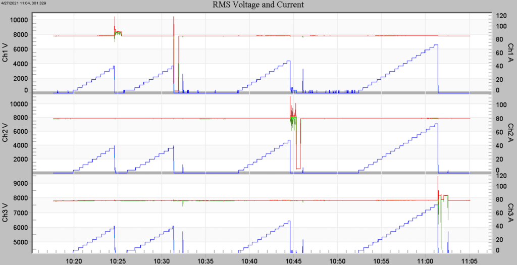
During witness testing of a 2 MW photovoltaic system, continuous power quality monitoring captured sustained ferroresonance triggered by a single dropped-phase test (Figure 5). The recorded data showed RMS voltages swinging from 6,000 to over 10,000 volts (8 kV nominal), wildly distorted non-sinusoidal waveforms, and complete loss of normal phase angle relationships. Without continuous waveform and RMS trend recording at the point of interconnection, this behavior might have been misinterpreted or missed entirely.
As DG penetration increases across cooperative service territories, witness testing becomes more frequent. Every test that involves a single-phase trip on a transformer with cable capacitance is a potential ferroresonance event. Mitigation approaches include customer-installed separate disconnect means, the use of load banks during testing, and test procedures that explicitly account for ferroresonance risk.
Design Strategies
Engineers can reduce ferroresonance susceptibility during the design phase through several practices. Keeping underground cable runs to lone three-phase padmounts as short as practical reduces the available capacitance. Specifying dead-front loop-feed padmount transformers makes cable-first energization procedurally easier. Using grounded-wye primary connections where the application allows reduces inter-phase coupling, and specifying triplex core construction eliminates the stray-flux problem associated with five-legged wound cores.
Capacitor bank placement also matters. Installing cap banks on feeder backbones rather than on laterals or taps served by single-pole fusing keeps the capacitance upstream of likely single-phasing points. Using switched rather than fixed banks on lightly loaded feeders reduces excess capacitance during low-load periods when ferroresonance susceptibility is highest.
When specifying transformers, engineers should weigh the ferroresonance implications of low-loss core designs — not to avoid them, but to ensure that switching procedures are appropriately matched to the equipment’s reduced damping characteristics.
Conclusion
Ferroresonance is built from a simple recipe: a transformer, capacitance, light load, and a single-phase switching event. It is rare enough to surprise people but serious enough to demand a clear operational playbook. The key defenses are equally straightforward: energize cables before connecting transformers, ensure load is present during energization, and use three-phase simultaneous switching when other options aren’t available. If the transformer sounds wrong, the voltage looks wrong, and the phase relationships don’t make sense — stop and change the plan. Awareness of the setup conditions and adherence to proper switching procedures can prevent virtually all ferroresonance events in the field.