Abstract
Impact loading occurs from the inrush current of large motors, welding apparatus, electric arc furnaces, or similar loads. The current pulses are less than short circuit values but may be on the order of 8 to 10 times the rated current of the transformer. This particular load pattern can cause early transformer failure, or the need to de-rate the transformer.
Impact loading with large inrush current can place severe mechanical stress on transformer windings and other components from the large magnetic fields involved. The repetitive mechanical stress can lead to early transformer failure. Several considerations are used to determine correct transformer sizing. A new ProVision report can help quantify the rate of current surges, and provide information for transformer de-rating or sizing under impact load conditions.
Motor Inrush Current
Induction motors tend to have a much higher current when the motor is first starting because the motor is at rest. When nearly full running speed is reached, the current drops rapidly to full load current or less, depending on the actual load attached.
The motor appears to be a transformer with a shorted secondary before it starts moving. This results in a very low impedance to the system voltage and the motor has a current of typically 5 times full load current, but can be up to 8 and sometimes as high as 10 times the current depending on transformer and power supply impedance.
Note that a soft-start motor controller can help reduce inrush current, and a Variable Frequency Drive (VFD) can eliminate it almost completely (at the cost of much higher harmonic distortion).
Unit Transformers
Generally large AC motors are isolated from the rest of the power system by unit transformers. Unit transformers have several advantages:
- Isolation of the load from the rest of the power distribution system minimizing system disturbances
- Selection of the best voltage for the motor
- Reduced inrush on the supply system
While it is possible to make a transformer that can withstand continuous short-circuits, the costs are impractical. Transformers are normally designed to withstand currents and resultant mechanical forces from a direct short circuit on one of its windings with full voltage maintained on the other windings. Normally the distortions encountered with one short circuit are not severe enough to cause mechanical stress failure. Repeated short circuits or high inrush/impact currents, however, such as caused by a large motor starting, may cause cumulative mechanical stress and eventually could cause the transformer to fail.
Very high currents can cause displacement of the windings. This results in the decrease of the performance of the transformer. Currents less than full short-circuit values will create correspondingly smaller forces and hence smaller displacements.
Unit Transformer Sizing Considerations
Transformer capability is determined from mechanical and thermal considerations.
Sizing of unit transformers for large, frequency switching motor application need to take in several considerations. These considerations also apply to other high impulse current loads, such as welders or arc furnaces.
The most important considerations are:
- Motor KVA at full load
- Starting KVA
- The number of motor starts per hour
- Short circuit capacity of power systems (KVA) at the transformer primary terminals
Transform Sizing Curve
The paper “Problems of Impact Loading on Unit Transformers” by Frank J. McCann and Robert J. Ristow gives a curve for unit transformer sizing with large motor starts (see Figure 1).
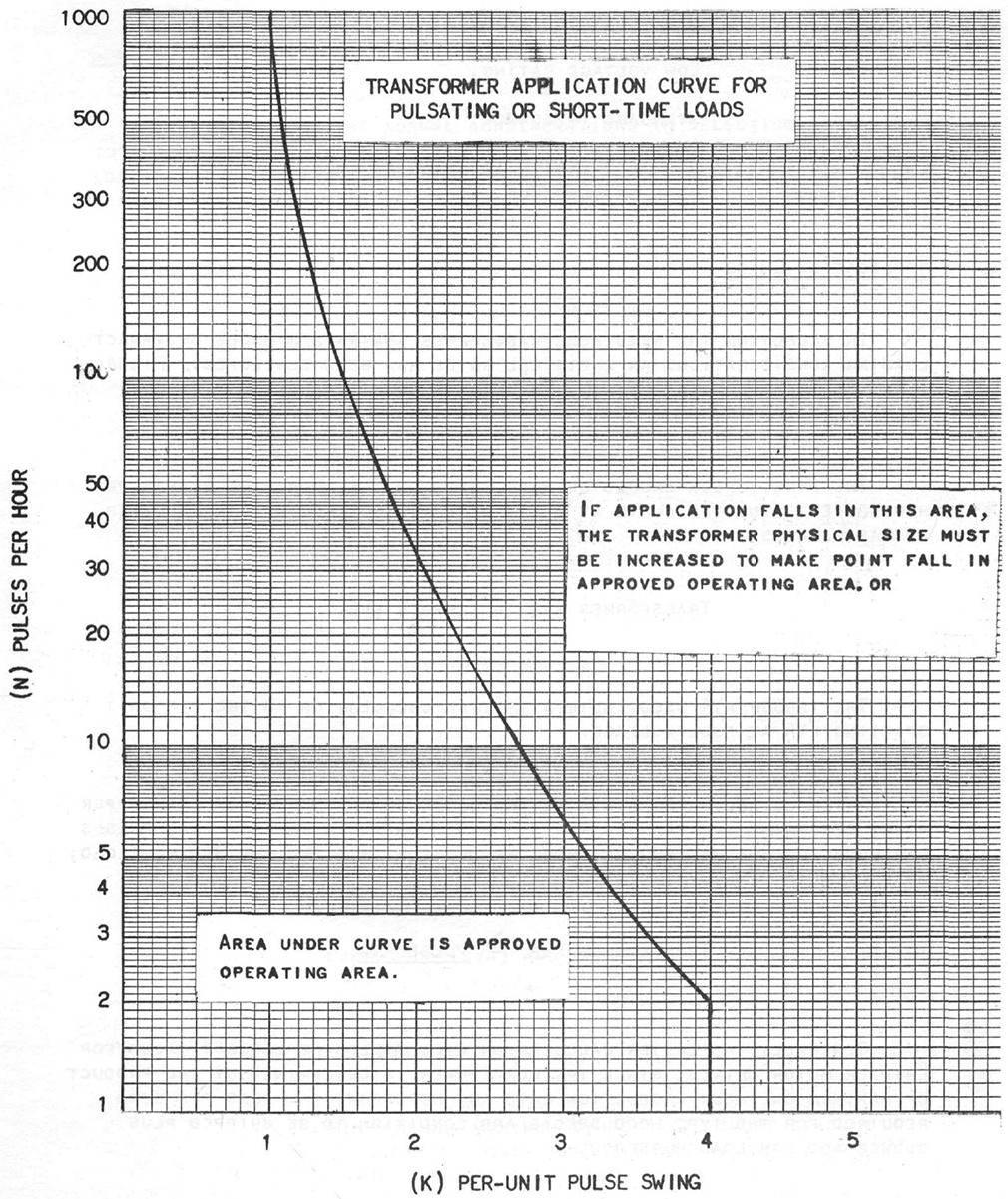
This curve has the Y-axis of motor starts per hour. The X-axis is Per-unit pulse swing (K). The Per-unit pulse swing is calculated with the following:
Values falling under the curve are safe for the transformer, according to the research in the paper.
The ProVision Current Over Limit Report can be used to count motor starts as explained below.
Recorder Settings for Measuring Impact Loading
The PQ recorder should be configured to record RMS voltage and current, with a 1 cycle interval setting. The one cycle interval is a good choice for motor start studies. These recordings are usually very short and completed while on-site. The one cycle interval is especially useful in conjunction with a very long waveform capture, allowing the entire motor start operation to be fully captured at every level of detail possible.
Choose settings to record nearly all of the available time interval graphs except individual harmonics, and IFL flicker. If the motor start is infrequent or cannot be started manually, then a 1-second interval may be more suitable.
To count long term motor-start rate the 1-minute interval may be best. In this application, the detail of each motor start isn’t important. Instead, the number of starts per hour is needed.
For catching intermittent problems at a one-cycle interval, or for long-term monitoring with very small intervals (such as 1 second), a networked or cell-based Revolution may be left in the field, relying on ProVision automatic downloads or email/text message alerts. The automatic downloads essentially give unlimited memory for stripchart recording. Alert notification allows for a manual remote download while the event is still in memory.
Also choose the correct current range to catch the peak inrush and motor start currents. For example if the steady-state current is 150A, the 1000A range may be a better choice to catch high inrush currents. Current waveform data should be configured to trigger when the motor start-up starts (typically by setting the current trigger level a bit higher than the motor running current). See WP115 for tips on analyzing motor startups.
Using ProVision for Analyzing Motor Starts
When a motor starts, the large current draw is short lived. The RMS Current stripchart will show the maximum current to be much higher than the average. Figure 2 shows an RMS current stripchart recorded at a two minute interval. It can be seen that the maximum current is much larger than the average. Each spike in the maximum current represents a motor start.

The Current Over Limit Report shows every current point where the maximum current exceeds the average current by a user-specified threshold. This report was designed to aid in counting the large motor starts. Figure 3 shows the current over limit report output.
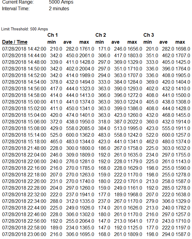
This report shows each motor start based on the maximum current reading much larger than the average current. By determining the number of starts per hour, the transformer sizing graph may be consulted to determine the correct de-rating or transformer size needed for the given impact load.
Large motor starting current inrush causes a voltage drop.
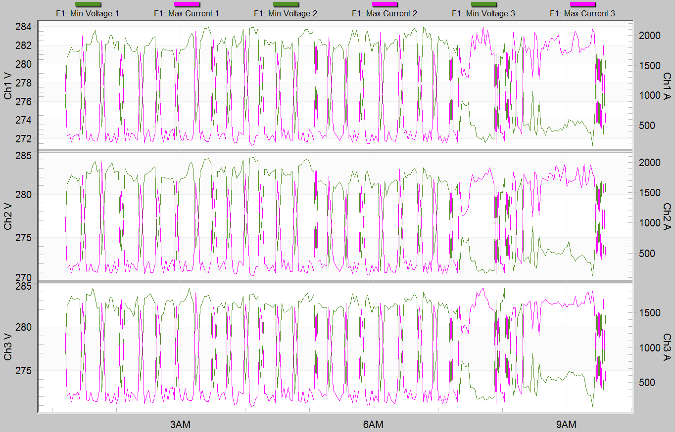
Figure 4 shows a stripchart of the minimum voltage and the maximum current. This graph clearly shows that the voltage drops as the current rises. The current and voltage changes are short enough in duration that the average voltage and current graph show little change at the two minute interval.
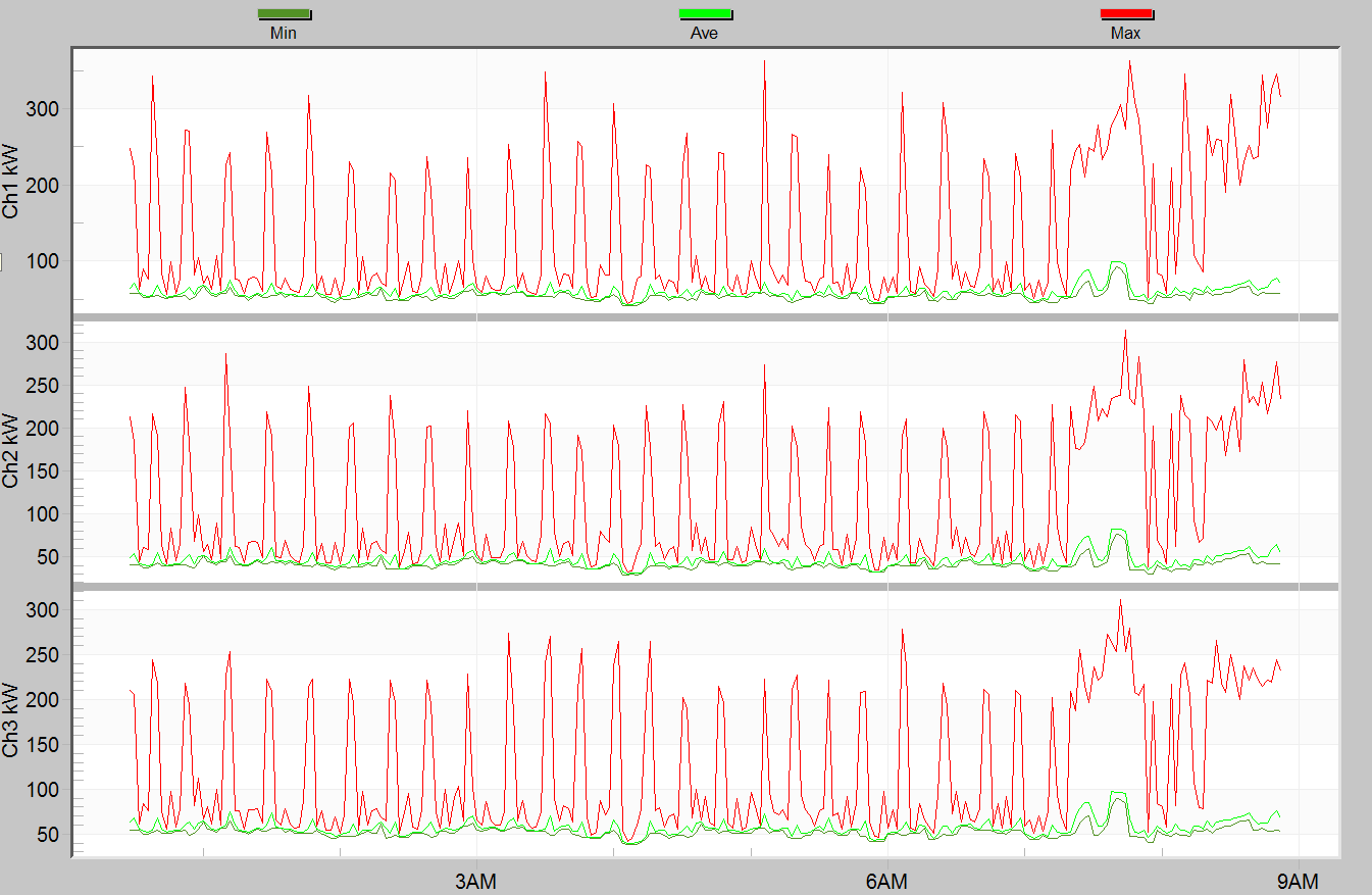
Figure 5 shows the real power stripchart. The motor start peak is shown to be four to five times that of the average running power.
Conclusion
Impact loading can cause problems for transformers due to repetitive mechanical stress on the windings, in addition to introducing voltage sags. Even though the thermal effects of impact loading are small (relative to the average current), a transformer may need to be de-rated or oversized based on frequent stress from near-short circuit currents. A new ProVision report has been created to assist with this sizing.
