Abstract
Whether you are new to the study of power quality, or an experienced PQ pro looking for a quick reference, IEEE Standard 1250 is the place to start. IEEE 1250 identifies and categorizes many common power quality (PQ) problems that can occur within a power line network, as well as strategies for mitigation.
Introduction
IEEE 1250 is a “gateway” document that provides an overview of power quality issues, then references more detailed IEEE standards to read for in-depth information. It is this “gateway” aspect that makes IEEE 1250 a foundational reference for anyone involved in power quality. The goal of this whitepaper is to provide a brief introduction to the power quality topics introduced in the IEEE 1250 Standard.
There are two categories of PQ issues to consider: Steady State Qualities and Disturbances.
Steady State Quality refers to power line behaviors that are sustained and associated with normal continuous operation. Disturbances, on the other hand, are line behaviors that are random, unpredictable, transient, and are associated with sudden changes.
PQ Steady State
There are four major topics to consider when looking at a steady state voltage signal, namely Regulation, Imbalance, Distortion, and Fluctuation.
Regulation refers to the overall magnitude of the sinusoidal waveform, usually measured in Root Mean Square (RMS) units.
Imbalance refers to a 3-phase network where the three phases are not equal in some way.
Distortion measures the shape of the nominally sinusoidal waveform and describes how different the shape is from the ideal sine wave.
Fluctuation refers to small variations typically sags and swells from the nominal level; these cause flickering lights and equipment malfunction.
Scale of Disturbances
IEEE 1250 describes seven different levels of tolerance that steady state qualities can exist within.
Emissions Limit — This limit characterizes what individual users are allowed to put out on the power line.
Network Disturbance — This number describes the point at which the effect can be sensed throughout the network.
Planning Limit — This is a voltage target range that the Utility would try to stay within.
Alarm Limit — Utility operators use this to know when there is an emergency that needs to be addressed.
Compatibility Limit — This number describes what the Utility would advertise as the maximum possible deviation from normal.
Test Limit — Equipment connected to the power network should be rated to handle a test at this level without sustaining damage.
Equipment Damage — Equipment could be expected to fail after this point.
Voltage Regulation
The ITIC curve defines standard regions of acceptable operation, low voltage shutdown and high voltage damage based on voltage level and time duration that electronic devices connected to the grid should satisfy. For longer term swells or sags (t > 10s), this curve defines a change of ±10% from the Nominal Supply as acceptable. The Compatibility limit for Utilities is that the 95th percentile of samples over a week should be less than ±5% from Nominal.
Voltage Imbalance
Voltage Imbalance occurs when there is a difference in magnitude or phase among the three phasors in a polyphase system. This could be caused by a large difference in current draw between phases, by a capacitor bank on the network, by the natural capacitance of underground wiring, by a blown fuse, by unmatched transformer impedance, and by single phase regulators that are optimizing the line-neutral voltages at the expense of line-line voltages. The main problem with voltage imbalance is that 3-phase devices like transformers and motors that run on an imbalanced supply tend to overheat much quicker and Variable Frequency Drives that run on an imbalanced supply tend to fail much earlier than expected. The IEC 61000-2-2 and the EN 50160 standards both recommend a 2% Imbalance Compatibility Limit for the 95th percentile of samples in a week. ANSI C84 recommends 3% imbalance. Motors may need to be derated when imbalance exceeds 1%.
Voltage Distortion
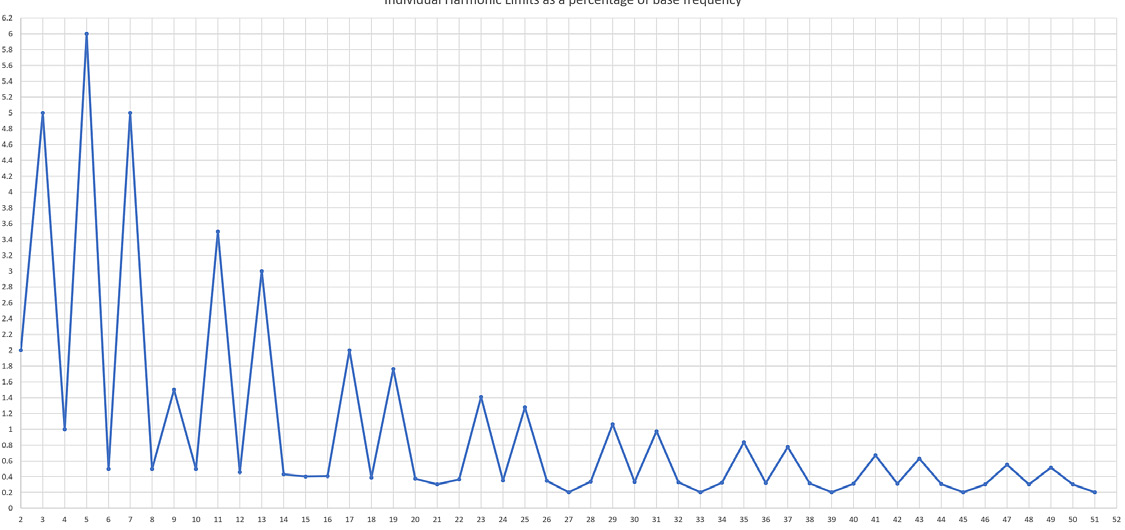
Nonlinear high current loads tend to reflect out onto the grid some amount of energy whose frequency is an integer multiple of the 60 Hz line frequency. This reflected energy causes distortion in the shape of the voltage signal. The main concern with this distortion effect is that the eddy currents, or currents that are induced in the iron core and then lost to heat, inside transformers approximately increases with the square of the frequency. Limits are set both on the total distortion and on the individual integer multiples of 60 Hz, because some harmonics cause more problems than others with specific equipment. The IEEE standard 519 recommends a total harmonic distortion at the point of common coupling less than 5% for Medium Voltage lines and less than 8% for Low Voltage lines. The graph below shows the individual harmonic limits as a percentage of the nominal supply.
Voltage Fluctuations
Voltage Fluctuations are cyclic variations in voltage level where ΔV < ±10%, so regulation is not a concern. These fluctuations are caused by sudden changes in load currents or generation currents. The limiting factor in this category is the human perception of flickering lights. The two important parameters defined in the IEC 61000-4-15 standard are the Pst, which is a short term measurement over 10 minutes and the Plt, which takes into account the last 12 Pst samples and performs a special average on them. The given compatibility limit is that the Pst should be less than 1.0 and the Plt should be less than 0.8 with 95% probability.
PQ Disturbances
Voltage Sags and Momentary Interruptions
The most important measurement index for this problem is the SAFRI_x which is the average number of voltage sags less than x% of the nominal supply. This index is time aggregated so that a single event causing multiple successive sags is counted only once. This type of event is common and the main concern is that computer systems and other digital circuitry tend to power off and must be rebooted when the voltage drops below a certain level.
Transients
Transients can be categorized as either impulsive or oscillatory. Impulsive transients are caused by lightning or large switching events and are usually characterized by rise time and decay time. Oscillatory transients are caused by charging a capacitor bank.
Frequency Deviation
The frequency of the line is directly tied to the rotational speed of the generators on the network. In most cases, the change in frequency is less than 15 mHz. The two major causes of frequency deviation are large power imbalances which can lead to around 100 mHz of deviation and the rare major blackouts which can lead up to 750 mHz.
Susceptibility of Consumer Loads
The standard describes specific consumer loads including Computers, Process Controllers, telecommunications equipment, electric arc lighting, consumer electronics, and adjustable speed drives and how these devices are impacted by power quality problems. Reclosing events occur when a fault is detected on the grid and a device automatically opens and closes a section of the line in an attempt to clear the fault. Reclosing events can last anywhere from about 3 cycles to several seconds. If a computer system does not have battery or super capacitor backup, then it is susceptible to shutdown during these reclosing events.
PQ Improvements
The last section of the standard describes improvements and solutions to mitigate power quality problems for end users.
Wiring and Grounding
This subsection describes easy and cheap solutions to try before anything else. The first is to ensure that all electrical connections and wires do not have any obvious visible flaws, such as extreme rust, melted cable housings, crimped and frayed wires. If a particular part of the system draws a significant amount of current, it might be worthwhile to place that part on its own separate connection to the grid. The last two recommendations are to use heat meters and shut equipment down if it gets too hot and to ensure the system is grounded properly according to IEEE 1100 standard.
Premium Power Solutions
This section describes two different devices that would act automatically in the event of a line voltage sag or dropout. The Static Transfer Switch will quickly transition to a separate power source if the primary fails. The Dynamic Voltage Restorer fixes line sags by injecting compensation voltage from a separate energy source.
End Use Power Conditioning
This section of the standard lists out many possible devices that may help an end user ranging widely from a surge suppression system like a fuse or breaker all the way to a full high reliability power backup system with a standby generator, batteries, transfer switches, rectifiers, inverters and other hardware. Some of the other devices mentioned include Constant voltage transformers, flywheels, uninterruptible power supplies, and power distribution units, which provide shielding to sensitive equipment.
Controlling Harmonics
Harmonics are measured at the point of use and limits on each harmonic defined in the distortion section above. This section describes several ways to deal with excess harmonic content. Some of these include moving affected load to a lower impedance circuit, moving the harmonic producing load to a different circuit, and installing larger or specially designed transformers. Harmonics can add together constructively to create unintended currents on the neutral wire, so it might be necessary to increase the wire thickness to meet the load. If a particular harmonic frequency causes problems, then it is possible to create a narrow band stop filter centered at the problem frequency.
Economic Analysis for PQ Solutions
The economic factors of PQ devices involve a balancing act between two competing factors. One is that energy costs becomes increasingly high as the PQ devices are pushed to the Power Suppliers. The other factor is that requirements on customers to make their devices work get increasingly complicated and unwieldy as PQ devices are pushed to the customers. The standard recommends performing a site survey to identify what are the susceptible loads and what are the most cost effective ways to solve the problems.
Conclusion
The IEEE 1250 standard defines many of the common Power Quality problems, as well as an appropriate metric and standard values for each problem. Make sure to look at devices like the Seeker or the Tensor sold by Power Monitors Inc. at www.powermonitors.com. These devices allow a user to measure a line voltage signal precisely and accurately, which will help him to make sure he is in compliance with the IEEE 1250 standard and diagnose any problems if he is not.
