Abstract
This white paper describes the proper hookup connections for differential input style PMI recorders. PMI offers the ability to monitor with two styles of voltage input connections to provide the user with the most flexibility when troubleshooting power quality issues. The VIP, IVS-3, and IVS-3/600P have differential voltage inputs where the Eagle, Revolution, and Vision have common mode voltage inputs. Although the differential and common mode voltage inputs can monitor the same circuit types; the connections on the circuit differ slightly. In order to fully understand the circuit hookup diagram, some circuit theory will be reviewed.
Differential Voltage Inputs
Differential inputs provide two inputs for each channel that respond to the signal difference between them. Differential inputs do not share a common point between the channels of the recorder. The voltage measurements in any circuit type would be the difference between channel connections. Since differential input recorders do not share a “common” point, they could be used to monitor two circuits that are completely isolated. Figure 1 below is a differential input circuit diagram.
Common Mode or Single Ended Inputs
Common mode inputs only provide one input for each channel and share a “common” point between channels. Depending on the circuit type, the common point could either be neutral or floating. In the case of the WYE circuit, the common point would be the neutral connection. All voltage measurements would be referenced to neutral and considered to be phase to neutral measurements. In the case of the Delta circuit, the common point would be floating. All measurements would be referenced to the corresponding phase voltage and the DELTA voltages would be calculated. Figure 2, below shows a common mode input circuit diagram.
Circuit Types
Depending on the distribution network and required service voltages, there could be a number of circuit types to monitor. Below are the circuit diagrams and a brief description on the proper connection sequence for the common circuit types found in most power systems.
Three Phase WYE
There are 12 connections associated with the 3 Phase WYE system (Figure 3, above) including the current channels. CH1 (A) Voltage and Current, CH2 (B) Voltage and Current, CH3 (C) Voltage and Current; CH4 is optional. Since the 3 phase WYE system has a neutral connection, all the neutral connections on the recorder need to be made at this point. The CH1 – black boot/white wire, CH2 – red boot/orange wire, CH3 – blue boot/green wire, CH4 – white boot/white wire with black stripe make up this connection. The line connections are the remaining points that need to be connected. The CH1 or A phase connection is the black boot/black wire, the CH2 or B phase connection is the Red Boot/Red wire, the CH3 or C phase connection is the blue boot/blue wire, and the CH4 (optional channel) is the white boot/red wire with black stripe that make up the line connections. The current channels are connected respectively with the voltage channel connections. In order to monitor with the WYE connected circuit type, the recorder must be initialized to WYE.
Three Phase Delta
There are 12 connections associated with the 3 Phase Delta system including the current channels as shown in Figure 4, above. CH1 (A) Voltage and Current, CH2 (B) Voltage and Current, CH3 (C) Voltage and Current; CH4 is optional. Since the 3 phase Delta system has no neutral connection, all the neutral connections on the recorder need to be made at the corresponding phase measurement. As shown in Figure 4, the CH1 – Black Boot/White Wire connects to the CH2 (B) phase connection to monitor phase to phase. CH2 – Red Boot/Orange Wire connects to the CH3 (C) phase connection to monitor phase to phase. CH3 – Blue Boot/Green Wire connects to the CH1 (A) phase connection to monitor phase to phase. CH4 – White Boot/White wire with Black Stripe is an optional connection and is not required. The line connections are the remaining points that need to be connected. As shown in Figure 4, the CH1 or A phase connection is the Black Boot/Black wire, the CH2 or B phase connection is the Red Boot/Red wire, the CH3 or C phase connection is the Blue Boot/Blue wire, and the CH4 (optional channel) is the White Boot/Red wire with Black Stripe that make up the line connections. The current channels are connected respectively with the Voltage channel connections as shown in Figure 4. In order to monitor with the 3 phase Delta connected circuit type, the recorder must be initialized to 3 Wire Delta.
Open Delta
The Open Delta, as shown in Figure 5 above, uses the same connection scheme and initialization as the 3 Wire Delta circuit. There are 12 connections associated with the Open Delta system including the current channels. CH1 (A) Voltage and Current, CH2 (B) Voltage and Current, CH3 (C) Voltage and Current; CH4 is optional. Since the open Delta system has no neutral connection, all the neutral connections on the recorder need to be made at the corresponding phase measurement. As shown in Figure 5, the CH1 – Black Boot/White Wire connects to the CH2 (B) phase connection to monitor phase to phase. CH2 – Red Boot/Orange Wire connects to the CH3 (C) phase connection to monitor the open phase. CH3 – Blue Boot/Green Wire connects to the CH1 (A) phase connection to monitor phase to phase. CH4 – White Boot/White wire with Black Stripe is an optional connection and is not required. The line connections are the remaining points that need to be connected. As shown in Figure 5 the CH1 or A phase connection is the Black Boot/Black wire, the CH2 or B phase connection is the Red Boot/Red wire, the CH3 or C phase connection is the Blue Boot/Blue wire, and the CH4 (optional channel) is the White Boot/Red wire with Black Stripe that make up the line connections. The current channels are connected respectively with the Voltage channel connections as shown in Figure 5. In order to monitor with the Open Delta connected circuit type, the recorder must be initialized to 3 Wire Delta.
Four Wire Delta
There are 12 connections associated with the 4 wire Delta system including the current channels, as shown in Figure 6, above. CH1 (A) Voltage and Current, CH2 (B) Voltage and Current, CH3 (C) Voltage and Current, with the CH4 being optional. Since the 4 wire Delta system has a neutral connection, all the neutral connections on the recorder need to be made at this point. As shown in Figure 6, the CH1 – Black Boot/White Wire, CH2 – Red Boot/Orange Wire, CH3 – Blue Boot/Green Wire, CH4 – White Boot/White wire with Black Stripe make up this connection. The line connections are the remaining points that need to be connected. As shown in Figure 6, the CH1 or A phase connection is the Black Boot/Black wire, the CH2 or B phase connection is the Red Boot/Red wire, the CH3 or C phase connection is the Blue Boot/Blue wire, and the CH4 (optional channel) is the White Boot/Red wire with Black Stripe that make up the line connections. The current channels are connected respectively with the Voltage channel connections as shown in Figure 6. In order to monitor with the 4 Wire Delta connected circuit type, the recorder must be initialized to 4 Wire Delta.
Two Element Delta
The Two Element Delta (Figure 7) uses the same connection scheme and initialization as the 3 Wire Delta circuit. There are 12 connections associated with the Two Element Delta system including the current channels. CH1 (A) Voltage and Current, CH2 (B) Voltage and Current, CH3 (C) Voltage and Current; CH4 is optional. Since the Two Element Delta system has no neutral connection, all the neutral connections on the recorder need to be made at the corresponding phase measurement. As shown in Figure 7, the CH1 – Black Boot/White Wire connects to the CH2 (B) phase connection to monitor phase to phase. CH2 – Red Boot/Orange Wire connects to the CH3 (C) phase connection to monitor phase to phase. CH3 – Blue Boot/Green Wire connects to the CH1 (A) phase connection to monitor the open phase. CH4 – White Boot/White wire with Black Stripe is an optional connection and is not required. The line connections are the remaining points that need to be connected. As shown in Figure 7, the CH1 or A phase connection is the Black Boot/Black wire, the CH2 or B phase connection is the Red Boot/Red wire, the CH3 or C phase connection is the Blue Boot/Blue wire, and the CH4 (optional channel) is the White Boot/Red wire with Black Stripe that make up the line connections. The current channels are connected respectively with the Voltage channel connections as shown in Figure 7. In order to monitor with the Two Element Delta connected circuit type, the recorder must be initialized to 3 Wire Delta.
2 ½ Element WYE
There are 10 connections associated with the 2 1/2 Element WYE system including the current channels. CH1 (A) Voltage and Current, CH2 Current, CH3 (C) Voltage and Current, with the CH4 being optional. Since the 2 1/2 Element WYE system has a neutral connection, all the neutral connections on the recorder need to be made at this point. As shown in Figure 8, the CH1 – Black Boot/White Wire, CH3 – Blue Boot/Green Wire, CH4 – White Boot/White wire with Black Stripe make up this connection. The line connections are the remaining points that need to be connected. The CH1 or A phase connection is the Black Boot/Black wire, the CH3 or C phase connection is the Blue Boot/Blue wire and the CH4 (optional channel) is the White Boot/Red wire with Black Stripe that make up the line connections. Note: The CH2 (B) Voltage is not connected in the 2 1/2 Element WYE system. The current channels are connected respectively with the Voltage channel connections as shown in Figure 8. In order to monitor with the 2 1/2 Element WYE connected circuit type, the recorder must be initialized to 2 1/2 Element WYE.
Two Wire Single Phase
There are 3 connections associated with the 2 wire Single phase system including the current channels. CH1 Voltage and Current and all other channels are optional. Since the 2 wire Single phase system has no neutral connection, all the neutral connections on the recorder need to be made at the corresponding phase measurement. As shown in Figure 9, the CH1 – Black Boot/White Wire make up this connection. The line connections are the remaining points that need to be connected. As shown in Figure 9, the CH1 connection is the Black Boot/Black wire that makes up the line connection. The CH1 Current is connected respectively with the Voltage channel connection as shown in Figure 9. In order to monitor with the 2 Wire Single phase connected circuit type, the recorder must be initialized to WYE.
Three Wire Single Phase
There are 5 connections associated with the 3 wire single phase system including the current channels. CH1 Voltage and Current, CH2 Voltage and Current and all other channels are optional. Since the 3 wire single phase system has a neutral connection, all the neutral connections on the recorder need to be made at this point. As shown in Figure 10, the CH1 – Black Boot/White Wire, CH2 – Red Boot/Orange Wire make up this connection. The line connections are the remaining points that need to be connected. As shown in Figure 10, the CH1 connection is the Black Boot/Black wire, the CH2 connection is the Red Boot/Red wire that make up the line connections. The current channels are connected respectively with the Voltage channel connections as shown in Figure 10. In order to monitor with the 3 wire single phase circuit type, the recorder must be initialized to WYE.
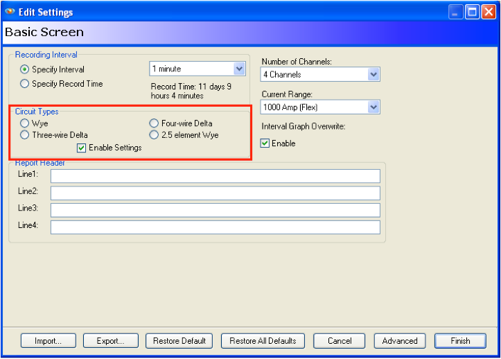
Setting the Circuit Type
In order for the calculations to be correct when monitoring a specific circuit, the recorder must be initialized to monitor that circuit type. The circuit type is set on the Basic Initialization screen as shown in Figure 11.
Conclusion
PMI offers the ability to monitor any circuit type found in the Industry. With a little background knowledge in the circuit types that are commonly used in Power Quality monitoring scenarios, connecting your recorder will be easier and more reliable. The time spent reviewing the connection diagrams will be well worth the effort when faced with a Power Quality issue.
For a PDF of the recorder Hookup Diagrams visit our website http://www.powermonitors.com.
