Abstract
High impedance faults can be a troublesome power quality issue affecting not only utilities, but their customers too. Frequently, these faults can trip arc fault breakers and GFCI outlets and pose substantial risks for damage to equipment (personal and utility). This white paper is going to talk about some of the common causes for these types of faults and will present some techniques for measuring and detecting them as well.
What Is a High Impedance Fault?
A high impedance fault is exactly what it sounds like: instead of a short circuit where there’s very high current flow due to effectively zero (or very low) impedance, this fault occurs when there’s a high (frequently two or three orders of magnitude greater) impedance. The impedance is such that current flow occurs, but at a level below any upstream protection trip points. In these scenarios, a locally high amount of power needs to be dissipated in a relatively small space. Unfortunately, this dissipation usually occurs in the form of heat.
Common Causes of High Impedance Faults
When it comes to household electronics, the common culprits are loose connections (probably the most common), worn or damaged wires, and component failures. When an electrical connection is loose (ex. not snugly inserted into an outlet), a high-resistance point is created where hotspots form due to locally high power dissipation and generate heat which, in turn, can create a fire (and shock) hazard. An intermittent connection can also cause arcing, another mechanism for a high impedance fault, where arc is the current flow path.
On the utility side of things, the most common culprits are downed conductors, tree branches (or other foliage), faulty insulators and animals.
But Why Are They So Dangerous?
High impedance faults are dangerous, because they’re not drawing so much current that traditional means of protection are engaged. The current flowing through, say, a traditional residential 15A breaker is still sufficiently low that it is not going to trip. Residential arc fault breakers may trip, but they’re not without their own flaws (including the occasional excessive false tripping, which is discussion for another date).
While the overall circuit current isn’t excessively high, the localized power at the point of fault is very high. And while the localized space is comparatively small, it’s still enough to create a shock or fire hazard.
Practical Example
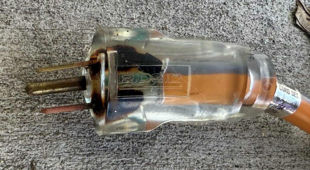
The author of this paper had a large vacuum cleaner plugged into a heavy duty (15A @ 125V rated) extension cord, well within the specifications of the vacuum’s name plate (6.5A @ 120V). After running the load continuously for about 25 minutes the vacuum was shut off, unplugged from the extension cord and, when the author approached the outlet to unplug the extension cord itself, he noted the smell of electrical burning and could feel heat radiating from the cord before he actually touched it.
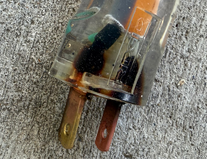
Once the cord had been removed from the receptacle (the author did verify that it was snugly inserted and not under any torque or other pressure during operation), it became evident that the fault was occurring at the point of contact between the stranded wire and the neutral blade. As it turns out, this is a pretty common point of failure.
So, how was this thing about to catch fire but everything was humming along happily? It’s because the fault was localized. A quick check with Ohm’s law we find that:

We’ll do a couple of adjustments to solve for the pieces we need and then derive another useful equation. First, we can solve for R (resistance or, in our case, its complex cousin impedance):

Assuming a close-to-nominal 120V on the circuit and a 6.5A load, we can conclude the following:


So our total power going through the circuit was about 780W and the system impedance (from the load of the vacuum) was about 18.5Ω. Now, if we substitute Ohm’s law into the V variable of the power equation, then we get:

We can use this equation and some estimates to determine how much power was being dissipated at the point of the fault.
Remember that the 780W are being used by the vacuum (most of it anyways) to do actual work (real power).
A loose connection (such as happened in this particular case) can result in an impedance of maybe 1 to 10Ω. If we start with 1Ω as the baseline, then the localized fault was dissipating energy at a significant rate. That’s not a tremendous amount, but recall that it’s localized and being entirely dissipated as heat. Even a relatively small amount of power concentrated in a small area can raise the local temperature high enough to degrade or melt insulation or create a fire hazard.
What if the impedance was closer to 10Ω? Now we are at 422.5W all being dissipated as heat. In reality, the current would decrease in this situation, resulting in less than 400W, but it would be high enough to cause severe localized heating.
So the current that was flowing through the cord was only 6.5A, which is well under the 15A residential breaker’s threshold for triggering.
Identifying High Impedance Faults
High impedance fault arcing generally yields a lot of harmonics, especially odd harmonics, but at relatively low magnitude. They’re low enough magnitude that inspecting RMS values won’t make it readily apparent that the fault is occurring. Additionally, looking at THD will likely not make for an easily recognizable signature either. While the harmonics are broad band, they’re low magnitude and therefore don’t sum up to be a significant portion of the fundamental magnitude.
Instead, the engineer conducting the investigation will need to use a power quality monitor capable of recording triggered waveform events. PMI’s recorders such as the Bolt, Seeker, Guardian and Revolution can all be configured to capture triggered waveforms based on absolute increase or decrease in RMS voltage, by waveshape or by percent increase or decrease in RMS current. (They can also be configured to periodically capture waveforms to be used as steady state comparisons.)
High impedance fault arcing presents, again, as high frequency noise at relatively low amplitude. They also show up as interharmonics since the arcing process itself isn’t synchronized to the line frequency.
Additionally, zero-crossing distortion can occur as the arcing process causes the current waveform to flatten (or become heavily distorted) at zero-crossing points. This is because the arc requires a certain voltage to “re-strike” after extinguishing at the zero-crossing. This can produce visual effects that look like “gaps” or “shoulders” that are not seen under normal load conditions.
Conclusion
The risks posed by high impedance faults are significant. Compounding this fact is the issue that detecting and mitigating these risks is extremely difficult. While the example provided in this paper is from a 120V residential circuit, the concept itself applies to and can be abstracted to a utility’s distribution network. This paper has demonstrated that, while difficult, detecting and preventing these types of faults can be achieved with the proper instrumentation, patience and a little bit of extra diligence.
