Abstract
Voltage unbalance can cause severe heating in motors and large DC power converters. Although most voltage unbalance is caused by unequal loading among phases, shifts in voltage phase angle can also cause unbalance. This unbalance is especially pernicious since it’s only seen in a delta hookup. In this situation, a wye measurement will show balanced voltages, while the delta circuit could be very unbalanced. The theory behind this is described here, along with lab tests and a real-world example.
Voltage Unbalance Defined
Ideally the voltages of a 3-phase system are all equal in magnitude and 120 degrees apart. Due to uneven single-phase loading, differences in impedance in connectors, transformations through open delta and other non-symmetric transformer arrangements, etc. the line voltages are often not exactly equal at the load connection point. Small differences in voltage are usually harmless, but as the difference increases, problems can quickly develop.
Voltage unbalance in a three-phase system can be defined as the max deviation from the 3-phase average, divided by the average. Defining Vave as the average of the 3-line voltages V1, V2, and V3, max deviation dVmax as the maximum difference from the average:
results in this expression for the voltage unbalance:
For example, if the three line voltages are 124V, 119V, and 114V, Vave is (124+119+112)/3 = 119.0, dVmax is 124-119 = 5V, and Vu is 100(5/119) = 4.2% at that point.
Problems with Voltage Unbalance
Voltage unbalance can be especially damaging to motors. A difference in phase voltages causes circulating currents in three-phase motors, with a resulting current unbalance of up to 6 to 10 times higher than the voltage unbalance. The extra current contributes to increased motor heating, and can be severe with a large unbalance. The temperature rise is proportional to the square of the voltage unbalance, and the increase from ambient temperature can be doubled with a 7% voltage unbalance. Increased temperature degrades insulation and decreases the motor life.
Many motors and VFD controllers are delta connected even with a wye service in the facility. If a voltage unbalance problem is suspected, a natural way to proceed is to monitor the voltage at the service entrance with a connection that mirrors the service. However, a wye connection could show no unbalance problem if the unbalance is due to phase shifts, not magnitude changes in the voltage vectors.
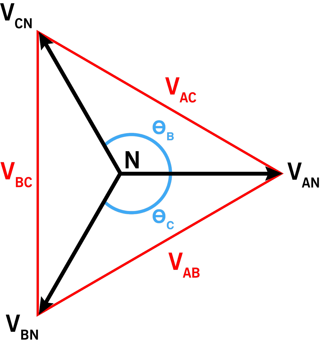
The unbalance calculation is based solely on the voltage magnitudes as seen by the recorder. Of course a 3-phase system involves phase angles as well as vector magnitudes, as shown in the familiar vector diagram in Figure 1. Here, VAN, VBN, and VCN, are the voltages with respect to a neutral point (not necessarily present in a real delta).
Theory
In a delta circuit, line-to-line voltages are formed by the vector subtraction of the line-to-neutral voltages by using Kirchhoff’s voltage law:
This subtraction is done on an instantaneous basis, but the sinusoidal nature of the waveform allows for a phasor representation which simplifies the analysis. With phasors,
where |VAN| is the magnitude of the vector VAN, and is the phase angle. Here all phases are referenced to phase A; its angle is defined to be zero.
To compute the line-to-line voltage VAB and the magnitude |VAB|, convert the polar vector values (magnitude and phase) to rectangular values (real and imaginary) and subtract:
As an example, consider a 277/480V system, with perfect 120 degree phase angles between the voltages. The voltage magnitude of VAB can be computed as:
Here we get 480V, as expected in a balanced system. However, the presence of the phase angle in the equation is the indication that it plays a part in the resulting voltage. If the phase angles are not 120 degrees between vectors, then the line-to-line voltages will not be equal. For example, consider a 5 degree phase shift in phase B:
A 5-degree phase shift increases the voltage from 480V to 491.4V, a 2.4% increase. Another phase will be lower, giving even more total unbalance. The wye (line-neutral) voltages are still 277V – perfectly balanced as a wye, but unbalanced when measured as a delta.
This calculation was encoded in Matlab, with the results shown in Figure 2. Here the resulting phase B voltage change in the above hypothetical 277/480V system is graphed vs. phase B phase shift from the nominal 120 degrees. At zero degrees, phase B voltage magnitude is 480V, as expected. At 5 degrees shift, the graph shows 491V, as in the above example. As the phase shift increases, the voltage keeps increasing, roughly linearly for the range 0-10 degrees. The per-unit voltage equivalent is shown on the right Y-axis. For a 5-degree change, the voltage is a little over 2% high (1.02 p.u.).
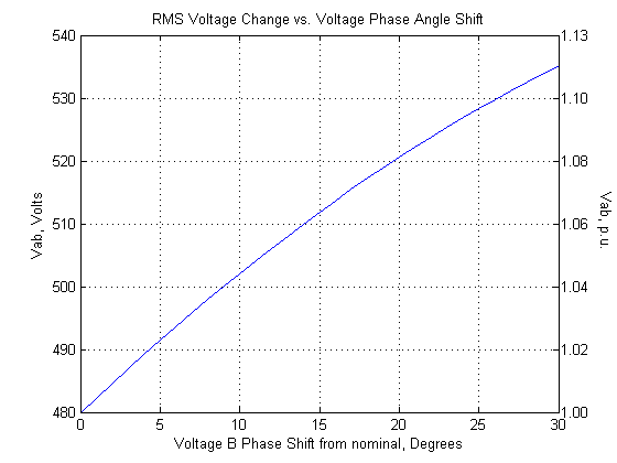
Although larger shifts should never happen in a functional 3 phase network, in theory as the phase error goes through a 0-360 degree range, the voltage error is shaped as a sine wave. The beginnings of a sinusoidal shape can be seen in the right half of Figure 2.
In the Lab
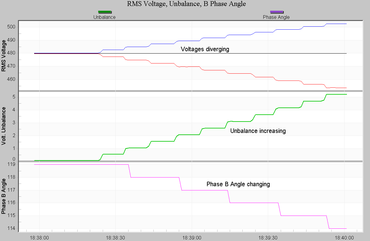
To validate this analysis, a test recording was made in the PMI lab. A Revolution was connected to a programmable AC power source, set to 277/480V output. The phase angle of the line-neutral phase B phasor was stepped in 1 degree increments from 120 degrees to 130 degrees. The result is shown in Figure 3. The top plot graphs the 3 line-line RMS voltages. The middle plot is voltage unbalance, and the bottom plot is the phase angle of phasor VAB. The step changes in each trace correspond to the 1 degree phase shifts that were applied. As the phase angle change increases, the phase voltages begin to separate from the ideal 480V, and the unbalance rises. Just a few degrees of angle error result in several percent unbalance.
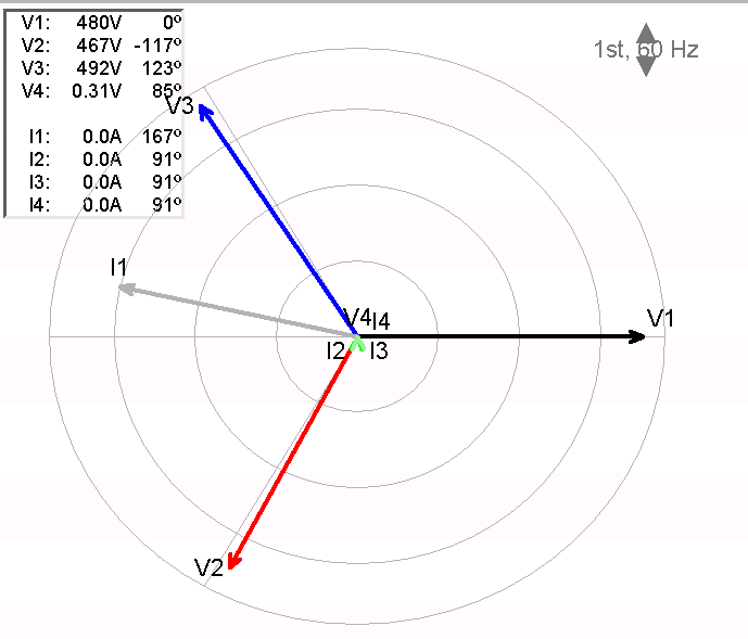
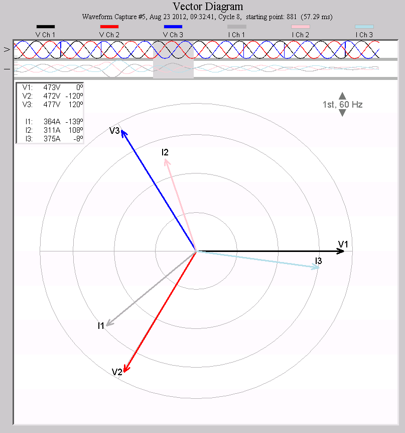
A sample vector diagram from the Revolution is shown in Figure 4. Altering a single line-neutral phase angle (B in this case) actually moves both the VAB and VBC phasors, so a wye-based phase change will alter two phasors when measured as a delta. Here channel 1 is unchanged at 480V, channel 2 is lower at 467V and channel 3 is higher at 492V.
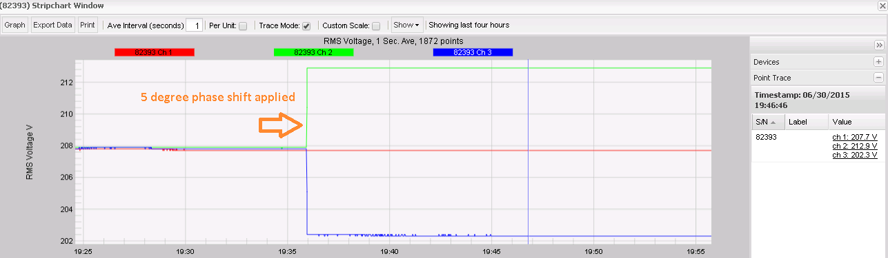
A Revolution was used for this test so that phase angle could be explicitly recorded and graphed, but a Boomerang is also an excellent tool for unbalance measurements. The same situation as above was tested, but with a 120/208V circuit. In Figure 5 the Boomerang is configured in delta mode, and the three line-line voltages are shown. A 5 degree shift in one phase is made near the middle of the graph, and the voltages jump apart by around 10V. These voltages would still be identical when measured with a wye connection.
In the Field
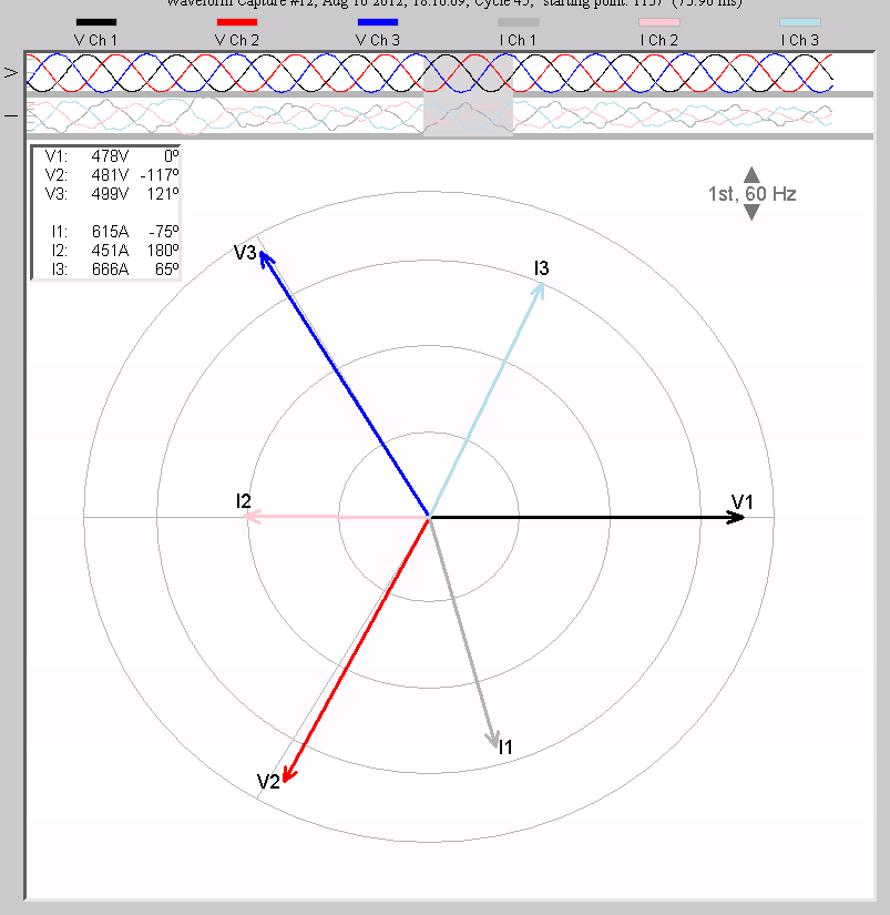
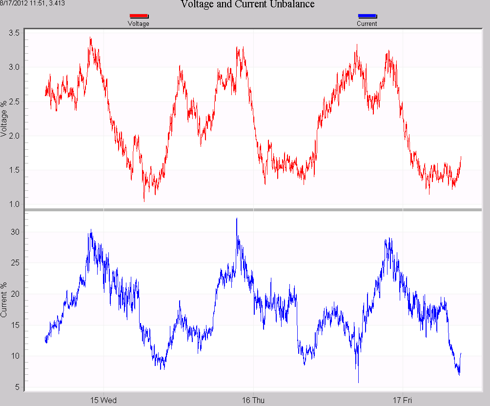
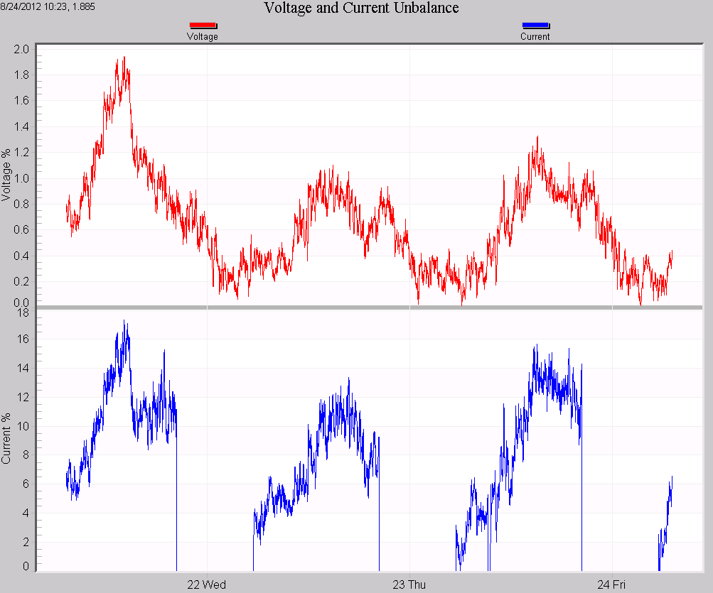
A real-world example illustrates how this theory appears in the field. At a substation, a neutral reactor in the primary bus had over 100 amps of unbalance current flowing through it. This neutral reactance presented an impedance that caused phase shift on both line-line voltages. A typical vector diagram from the substation is shown in Figure 6. Channel 2 is 3 degrees off (117 vs. 120), and channel 3 is shifted by 1 degree. Channel 3 is reading 499V, significantly high compared to the other phases. The voltage and current unbalance graph is shown in Figure 7. The voltage unbalance is over 3% during the day. The current unbalance is correlated with this, and is causing a normal amount of unbalance due to the differing loads, but the neutral reactance exacerbates this problem by introducing phase shift in the line-line voltages.
The problem was fixed, and the resulting vector diagram and unbalance graph is much better in Figures 8 and 9. Here the phase angles are back to normal at 120 degrees, and the voltage unbalance is significantly lower.
Other sources of voltage phase shift include an open capacitor bank (e.g. blown fuse) on a single phase, or open delta transformers where the transformer reactance is not equal for each phase.
Conclusion
Voltage unbalance should be measured with the same hookup type that a sensitive load is using. Motors and VFD controllers are the most common type of equipment sensitive to voltage unbalance, and these are usually connected as delta, even when the service is a wye. In this situation, it’s important to measure unbalance not as the service is wired, but as the sensitive equipment is wired – delta. The wye voltages could appear perfect, while the delta voltages are significantly unbalanced solely due to voltage phase shifts. Whether using a Revolution, Eagle, or Boomerang, configure it to match the hookup type of the load most sensitive to unbalance – usually a delta.
