Abstract
Power Factor measures the efficiency in an electrical circuit, based on how much of the power delivered to a load is used by the load for work. Loads that produce harmonics affect the power factor of the circuit. This whitepaper will introduce the concept of power factor, displacement power factor, and the effect of harmonics.
Basic Concepts
To understand power factor, the differences between real power, apparent power, and reactive power must be understood. The definitions of these are as follows:
Apparent Power, measured in volt-amperes [VA] is the total power delivered or consumed by the load and is the product of the voltage and current in the circuit. It is the absolute value of complex power, marked as S on the graph shown in Figure 1, below.
Real power is the capacity of the circuit for performing work at a certain time. It is measured in watts [W] and is marked as P in Figure 1.
Reactive power is power that is returned to the source without being consumed by the load. This is marked as Q on the graph shown in Figure 1.
Power Factor Defined
Power factor is the proportional relationship of real power (also called active power) to apparent power. It is used as a practical measurement of efficiency in an electrical system. This is a dimensionless number between 0 and 1. When the power factor is 0, the energy flow is entirely reactive and all of the power is returned to the source. When the power factor is 1, all energy supplied is consumed by the load.
When the waveform is purely sinusoidal, the power factor is the cosine of the phase angle (φ) between the current and voltage sinusoid waveforms. In purely capacitive circuits, reactive power is produced with the current waveform leading the voltage by 90 degrees. In purely inductive circuits, reactive power is produced with the current waveform trailing the voltage waveform by 90 degrees. In either of these cases, there is no net transfer of power to the load and all energy is reactive.
Displacement Power Factor
Displacement power factor is the power factor of a circuit with a linear load without harmonics present. It is calculated with the formula:
PF = cos(θ)
Harmonics
Harmonics are “Non-Linear” current or voltage in an electrical system. Harmonics can be thought of as a device that draws current unproportionally to voltage. Any wave that deviates from a perfect sine wave has harmonics. Any non-linear load draws harmonic currents and therefore produces harmonic voltage distortion.
Harmonics are voltages or currents that are multiples of the fundamental frequency in a circuit. These are specified by their harmonic number or multiple of the fundamental frequency, as shown in Figure 2. For example, with 60hz fundamental frequency of the third harmonic is 180hz. In this example, for every cycle of the fundamental frequency, there are three cycles of the harmonic frequency.
What Is True Power Factor
True power factor is power factor when distorted voltages and currents are present. This distortion affects the shape of the original waveform based on their frequency, amplitude, and angular position with respect to the fundamental waveform.
Due to this waveform distortion caused by harmonics, the apparent power that must be delivered to the load is increased. This results in extra current that is not being transferred to actual work. The true power factor in these cases will usually be lower than the displacement power factor.
Power Factor vs Displacement Power Factor
Power factor and displacement power factor are two different measurements. In a case where there are no harmonics present, they are equal to each other. If power factor and displacement power factor are different, harmonics must be present. When harmonics are present, power factor is usually less than displacement power factor.
Power factor is the true measurement for representing the “efficiency” in delivering power in terms of current flow. Displacement power factor is better for calculating the size of power correction capacitors.
Often, the need to record both power factor and displacement power factor is not needed. The correct one to use is dependent on the reason for monitoring. Revenue meters used to use displacement power factor for measurements. Now, electronic revenue meters can be programmed to record power factor in the case where there are penalties for customers with poor power factors.
In a three phase delta, power factor is not as well defined as displacement power factor. This is because the watts/VA computation depends on the definition of VA.
Power Factor in PMI Recorders
PMI devices record power in a number of ways: real power, apparent power, reactive power, phase angle, power factor, and displacement power factor. Each of these stripchart records uses up recording space. Even if individual stripcharts are not enabled, recorders that measure power factor and displacement power factor still record daily profiles and histograms of them. Depending on your needs, you may be able to turn off recording of some of these, as shown in Figure 3.
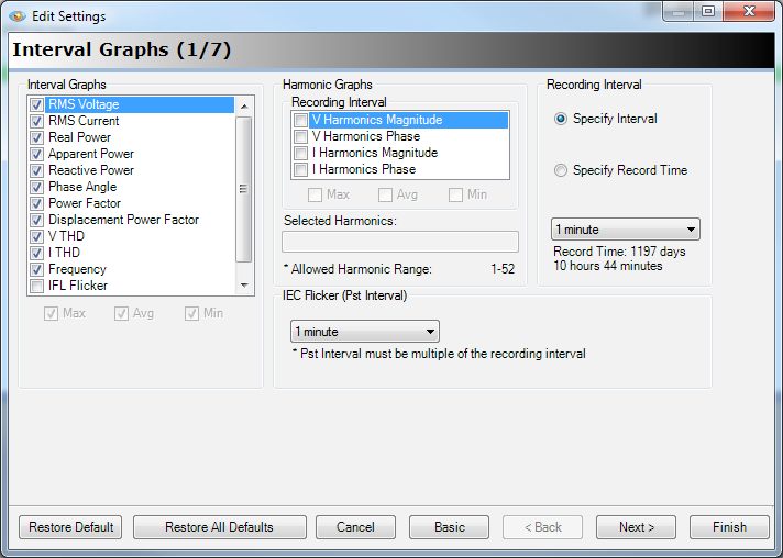
To Turn Off Specific Recordings Using ProVision
- From within ProVision click on the “Recorder” menu, move down to “Connect Recorder”, and select the recorder you wish to work with.
- Under the “Recorder” menu, select “Retrieve Settings”.
- On the “Retrieve Settings” screen, click on the “Open” button. This will bring up the “Edit Settings” screen.
- Click on the “Advanced” button on the “Edit Settings” screen.
- De-select the settings you no longer wish to be recorded and click the finished button.
