Abstract
The NMS (or Network Management Software) is a lightweight Java Desktop Application produced by PMI for the bulk configuration of Boomerang voltage/current/power monitors. This document aims to provide the user with an overview of the different configuration and polling tools that are made available through the NMS and will discuss some of the more common tasks, such as configuring Boomerangs for DNP3 / SCADA.
Installation
As mentioned, the NMS is a lightweight Java Desktop Application that does not come with a traditional installer. Instead, the installer, like the NMS itself, is written as a Java Desktop Application and can be obtained at the following url: http://nms.powermonitors.com/files/nms_installer_2.14.zip. Begin by extracting the contents of the zip file into a directory (not the ultimate installation directory – a temporary directory would be preferred) and then double-click on the nms_installer.jar file to begin installation. Follow the onscreen instructions for selecting a default installation location. The NMS currently includes a patch to enable newer features. Download the latest NMS patch from the following url: http://nms.powermonitors.com/files/nms_update_3.51.zip. Next, extract these into the NMS Installation Directory. These are a series of patches that simply overwrite the existing NMS.jar executable and other updated files.
Important Note: there are certain files that are critical to the proper functioning of the NMS that are installation-specific. These files contain keys, databases of boomerangs (with their IP addresses, serial numbers and other important information) and other vital components that should be backed up before any upgrade to the NMS. These files are: pminms.cfg, keyfile.aes (extremely important), pminms.ndb. These files will be listed below along with a brief explanation of each.
Importing Boomerang Information
Before the NMS can actually be used, some import details about the Boomerangs that are to be operated on must first be imported into the system. To do this, start by creating an “EDF” file – which is essentially a CSV (comma separated value) file – that contains the following information:
serial number, phone number, ipv4 address
The EDF file must contain the line above as the very first line in the file – it is a mandatory line. Following that line, the actual device information to be entered, row by row, for each device that is to be imported. Here is an example of a short (but valid) EDF file:
serial number, phone number, ipv4 address
14165,,192.168.4.1
72020,,192.168.4.8
14173,,192.168.4.3
Note in the example above that the phone number has been omitted. This is the only optional field in the EDF file.
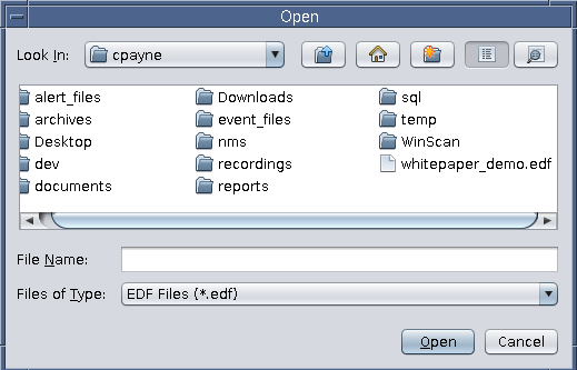
Once the EDF file has been created, it is time to import it into the NMS. From the Admin Menu, select “Import EDF.” The user will be presented with an “Open” prompt from which the newly created EDF file should be selected (Figure 1).
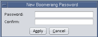
After the user has selected the EDF file to import, they will be prompted with a “New Boomerang Password” dialog, as shown in Figure 2. Each Boomerang is shipped with a default password (sent to the customer upon Boomerang shipment), and should be entered at this time in the box. Note that this is not where the device’s password is actually being set – this is where the user is telling the NMS what password to use when connecting to a Boomerang for the first time. Setting the password in a boomerang is discussed later in this paper.
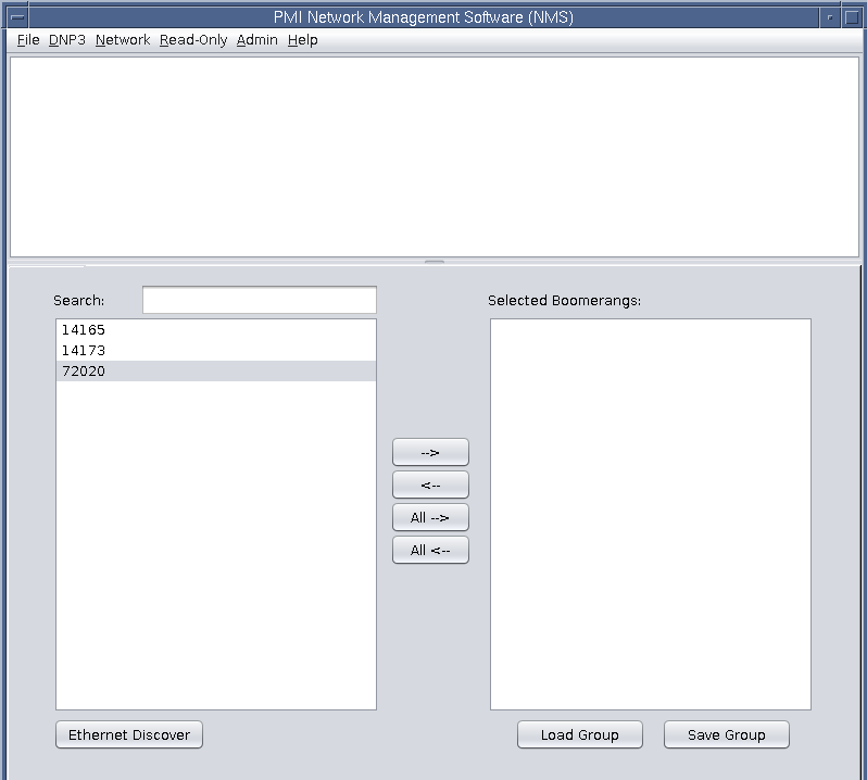
Once the Boomerang default password has been entered (and confirmed) the newly imported Boomerangs should now be visible in the device panel at the bottom-left of the screen, as shown in Figure 3.
Operating on a Boomerang
Now that the Boomerang information has been imported into the NMS it is time to actually look at configuring and polling the devices to meet the customer’s requirements. A recommended first step is to “identify” the devices (Read-Only menu). Performing this operation allows the user to ensure that the selected devices are online and that the information from the EDF file is correct (the reported serial number from the devices matches the serial number from the EDF for an IPv4 address).
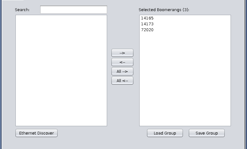
Operations can be performed on a single device or “in-bulk.” To select one (or many devices) simply highlight them in the Device Selection Panel on the left side of the screen and then click on the “→” arrow button to transfer them to the “Selected Boomerangs” panel. Any devices in the “Selected Boomerangs” panel will have the selected operation performed on them. Another alternative, if the user so desires, is to click on the “All →” (or “All ←”) buttons. These buttons auto-select all and move from the Device Panel to the Selected Boomerangs panel (→) as shown in Figure 4 or from the Selected Boomerangs Panel to the Device Panel (←).
As mentioned above, identifying a group of newly imported devices is a great first place to start. To do this, click on the Read-Only menu and then select “Identify” or simply press the F5 key from within the NMS application.
The “Command Status” window will now appear, showing the current progress for the requested command. As the reader can see in Figure 5 below, two of the devices have successfully connected and one is still in the “Connecting” state. (Note that cell-modem enabled devices, such as the Boomerang, can experience a lot of latency through the cellular network. It is recommended setting the timeout to at least 60 seconds to allow the TCP buildup and teardown mechanism enough time to work.)
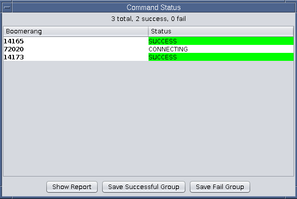
Also note the three buttons on the bottom of the “Command Status” group. The first is the “Show Report” button which will jump immediately to displaying the results of the Identify command from above. The other options allow the user to “save the successful devices as a ‘group’” or “save the failed devices as a ‘group.’” The concept of “groups” will be discussed shortly and will help to show the utility of these buttons. For now, however, simply select the “Show Report” button.
As the user can see, the report presents the results from each device stacked in alternating-highlighted rows with the detailed information for each (such as Firmware, IP Address, Serial Number (this is the number imported from the NMS) vs SN (the Serial Number as reported by the device), etc.). This is shown in Figure 6. These reports can be saved in HTML format by clicking on File → Save Output from the report window or they can be saved in CSV format by clicking File → Export to CSV from the report window.
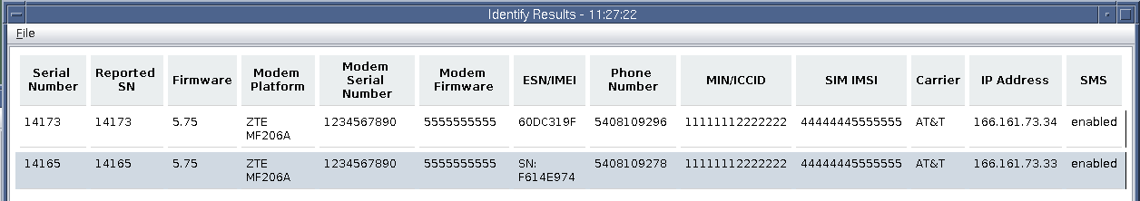
A final note on reading report results: if the reader were to compare Figure 5 (command status window output) to Figure 6 (the actual report) they will notice that only two rows show up on the report, compared to the three devices listed in the Command Status window. This is because the third device, 72020, never ended up connecting so it was unable to produce identifying information for the report. Its entry, therefore, was excluded from the final report.
All reports are rendered in a similar fashion to the Identify report that was discussed above: they can all be exported to CSV or to HTML and all of them will exclude devices that failed to report the desired information.
Reports, however, are just one piece of the NMS functionality – device configuration is the second piece.
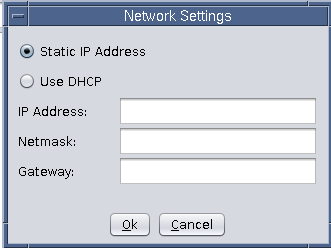
Configuring devices is done in much the same manner as generating reports. Devices are selected from the Device Selection panel and then an operation is selected from one of the four primary pulldown menus. Some options require user input (such as Network Settings – shown in Figure 7) while others, such as the “Reboot” command from the Network menu – simply send a command and require no user input.
Logs
The NMS keeps a rolling log of all operations performed on devices through the NMS. The text area at the top of the NMS contains read-only logs for each operation performed throughout the session. This information, if desired, can be saved by clicking File → Save Output from the NMS main window. Alternatively, the output can be “Cleared” if it is generating too much clutter and is otherwise being used as a source for debugging devices that may, as an example, be on the fringe of cellular service. The logs are saved in plain-text ASCII format.
Device Groups
Some utilities have many thousands of Boomerangs to manage. To help manage a subset of Boomerangs, it is possible to create a group of devices that can help a user identify devices by a geographical region or area of responsibility (instead of having to reference serial numbers). To do this, simply select the devices from the Device Selection panel that are to be placed in a group, move them to the “Selected Boomerangs” panel and click on the “Save Group” button.
Figure 8 shows the selection of two devices (and the exclusion of one – the Boomerang that failed to connect for identification) being saved as a file called “good_guys.txt.” As expected, the contents of this file are pretty straightforward: it is a plaintext list of serial numbers, one per line. (This means that a user can easily create their own groups by creating text files in a similar format. It isn’t necessary to generate them from the NMS – it is only provided as a convenient, graphical way of creating a group from the current “working set” of selected devices.)

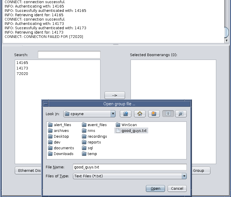
To select a group, simply click on the “Load Group” button at the bottom of the window and then select the appropriate group file, as shown in Figure 9.
At this point the devices will be transferred from the Device Selection panel on the left to the Selected Boomerangs panel on the right.
Firmware Management
From time to time PMI will issue firmware patches and upgrades for the Boomerang. The NMS has divided this process into a couple of steps, primarily out of an abundance of caution and for security’s sake. To begin, PMI will publish the firmware package to http://nms.powermonitors.com/. All new device firmware (and older versions as well) are listed under the Firmware section.
Start by selecting the firmware that is appropriate for the Boomerang to be upgraded (the firmware is generally divided by wireless provider). Download the firmware binary package (.bin file) to the same machine that is running the NMS.
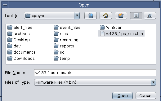
Once the firmware package has been downloaded it needs to be imported into the NMS – this is a task that only an administrator can undertake. Click on the Admin menu and then select Add Firmware. This will present the user with an Open dialog that filters for .bin files. Select the recently downloaded firmware .bin file.
As soon as a file has been selected, the user will be prompted with a “Firmware File Description” dialog. The default description is the name of the firmware package file that was just selected (in the example of Figure 10, the default description will be vz133_1ps_nms.bin). This can be anything that the user desires that will help identify the firmware to the end user that will be responsible for pushing the firmware to a boomerang. It is recommended that a descriptive name (i.e. 3G Boomerang — 8 October 2015) to prevent confusion as a list of all imported firmware remains available to users once it has been imported.
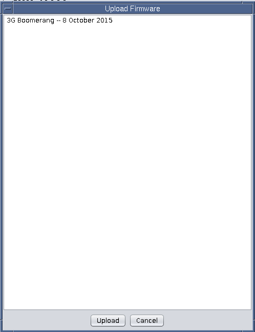
Now that the firmware has been imported into the NMS, it is time to push it to a device. Begin by selecting the device(s) whose firmware is to be upgraded, then click on the Network menu and select Push Firmware. This will bring up an “Upload Firmware” selection dialog that presents the user with a list of available options, based on the upload description provided by the NMS administrator when adding the firmware in the previous step (Figure 11).
Select the desired firmware to be sent to the selected device(s) and then click Upload. As with all other commands, the “Command Status” dialog will appear and will provide the user with an in-depth, live status of the firmware upload process, including the percent complete, etc.
Once the firmware upload has been completed, if the device has verified the checksum and that it is a valid firmware package for the device, an acknowledgment will be sent to the NMS and then the device will automatically reboot to make the new firmware changes take immediate effect.
Conclusion
The NMS is a very lightweight, easy-to-use and intuitive application that can be used for polling and configuring Boomerang voltage/current/power monitors.
