Abstract
Voltage unbalance in a four-wire or “high leg” delta can be tricky to measure. A 4-wire delta often involves unbalanced impedances, and phase shifts in the hot leg are common. Unbalance measurements referenced to the neutral require scaling for the hot leg, and can be misleadingly low for delta-connected loads. A technique for computing true line voltage unbalance from neutral-referenced readings is shown, along with a real-world example.
In a 4-wire delta one transformer is center-tapped. As in a single-phase 120/240V transformer, the center tap is defined as neutral. The other two transformers (or windings in a single transformer) are connected in a standard delta configuration. The typical 4-wire delta is shown in Figure 1. The most common 4-wire delta is sized to give 240 VAC from line to line. Two of the phases measure 120 VAC from line to neutral, and the “high” leg is 120√3 ≈ 208 VAC. The two 120V legs are 180° apart, like a single-phase system, and both are 90° out of phase from the “high” leg. A delta connected load would see the normal 120° phase angles formed by the vectors connected the corners of the delta. A hypothetical wye-connected load would see 90° and 180° angles, along with 120V and 208V magnitudes, but in practice no 3-phase loads are connected this way. The 4-wire delta allows for 240 VAC delta connected loads, while providing a low voltage 120V source for lighting, receptacles, etc.
By design, all single-phase loads are fed from just one of the three delta transformers (or windings). This essentially guarantees some load imbalance — it’s not possible to rearrange breakers, move loads in panels, etc. to equally distribute the loads if they’re all fed from the same transformer. A 240V load will only connect to one pair of phases, and even if these are distributed evenly around the delta, the delta itself is unbalanced. The source impedance presented by the transformers often differs due to the center-tap and presence of single-phase loads.
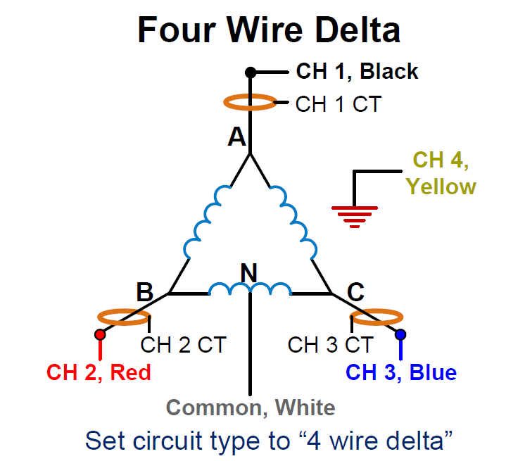
A typical 4-wire monitoring connection is shown in Figure 2. This configuration is required to compute total power properly, but results in neutral-referenced voltage readings. With a perfect system, the voltages will read 120V, 120V, and 208V. Obviously voltage unbalance calculations will need some adjustment given the high leg.
Voltage unbalance is usually defined as the max deviation from the 3-phase average, divided by the average. Defining Vave as the average of the 3 voltage readings V1, V2, and V3, max deviation dVmax as the maximum difference from the average:
results in this expression for the voltage unbalance:
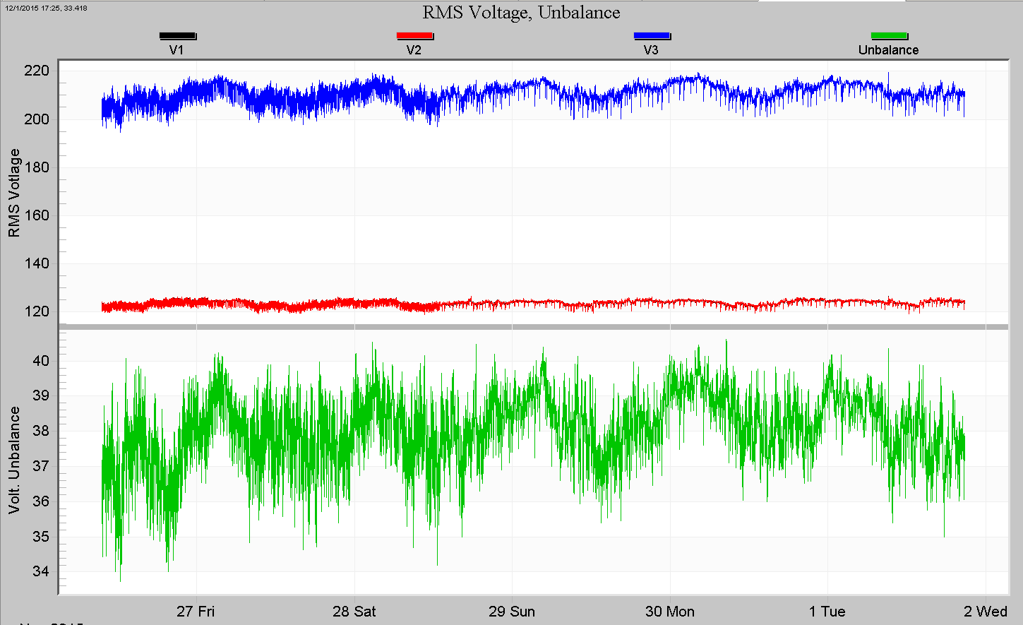
Plugging in the ideal 4-wire delta (neutral-referenced) readings of 120, 120, and 208V gives an unbalance of (208-120)/((120+120+208)/3) × 100% = 58.9%. Here the true line-line voltages would be perfectly matched with zero unbalance – all 240V – so the base formula cannot be used directly. Graphing the voltages and unbalance in ProVision results for a real data file show the problem, as seen in Figure 3. The blue top trace is the high leg, and the voltage unbalance in the bottom plot is almost 40%.
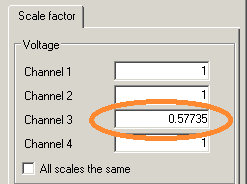
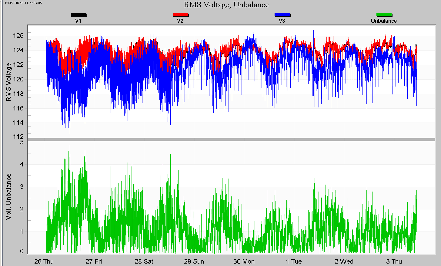
A “quick and dirty” adjustment is to scale the high leg so that it’s in line with the other two readings. In a perfect 4-wire delta, the high leg is √3 larger, so a scale factor to undo this is about 0.57735. Figure 4 shows the adjustment dialog in ProVision. Redrawing the voltage unbalance graph gives much better results, as shown in Figure 5. The blue voltage trace is now in line with the others, and the voltage unbalance is a much more reasonable 2-3%, with some short periods approaching 4%. As shown below, this method gives a lower bound on delta unbalance – the actual unbalance may be much worse. Unbalance trends may still be seen though.
Although this is a true unbalance measurement for a wye-connected load, it’s not necessarily accurate for real loads — real 3-phase loads will be delta-connected, due to the high leg in the wye configuration. Converting the wye measurements to delta involves the vector phase angles, and it’s possible for phase angle shifts to create much more delta unbalance than measured as a wye.
The 4-wire delta is especially prone to phase shift unbalance problems. The high leg has a 90° angle from the other two legs, compared to 120° for a standard delta. The amount of voltage magnitude shift per degree of phase shift actually varies with absolute phase angle, and 90° is the worst case (180° is the best case). Thus, a 4-wire delta is even more sensitive than a normal 3-wire delta for phase shift-induced voltage unbalance.
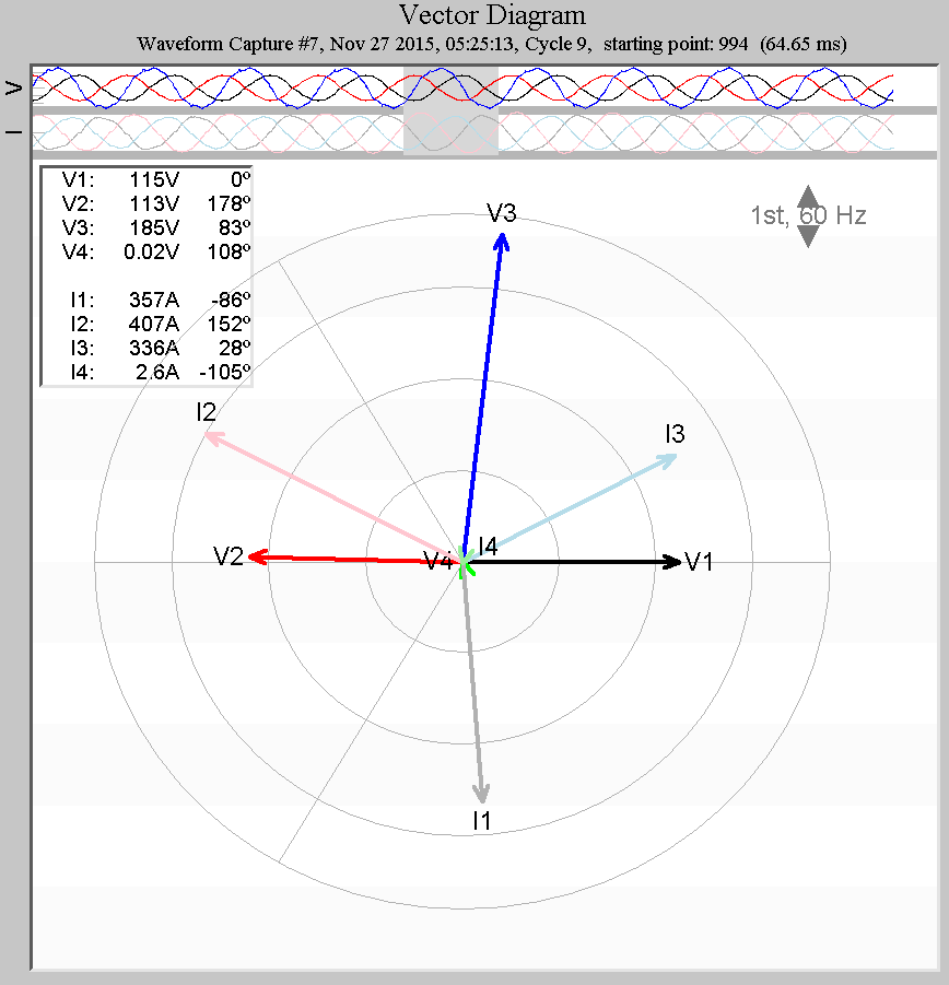
To compute delta unbalance, it’s first necessary to compute delta voltages. This requires phase angle information, which leads to the ProVision vector diagram. A typical vector graph from the same data file seen earlier is shown in Figure 6. The voltage vectors are in the normal 4-wire delta arrangement, with V3 as the high leg. The current vectors are 120 degrees apart, indicating mostly 3 phase load. The channel one voltage is the phase reference, so it’s by definition at zero degrees. Here V2 is the opposite single-phase leg, at 178 degrees, and V3 is the high leg, at 83°. The seven degree phase shift from the high leg is significant, and likely to cause excessive voltage unbalance itself, apart from any actual voltage magnitude issues.
To convert these readings to delta, vector math can be used to solve for Vab, Vbc, and Vca, given Van, Vbn, and Vcn. As described in the whitepaper Hidden Delta Voltage Unbalance, the phasor Vab is
where |VAN| is the magnitude of the vector VAN, and ∠θA is the phase angle. Converting the polar vector quantities to rectangular quantities and subtracting results in
with similar equations for the other two voltages. Plugging the readings from the vector graph in Figure 6:
| Voltage | Magnitude | Angle |
|---|---|---|
| Van | 115 | 0° |
| Vbn | 113 | 178° |
| Vcn | 185 | 83° |
gives
An ideal 120/240V 4-wire delta would measure 240V for all line-line voltages. Here we have 228, 225, and 206V. Even 228V is 5% low from a 240V nominal, and clearly there is some significant unbalance with one phase reading 228V, and another at 206V. To compute the actual unbalance, the max deviation dVmax and average Vave are needed.
Here we get Vave = (228+225+205.6)/3 = 219.5V, and dVmax = 219.5-205.6 = 13.9V, resulting in an unbalance of 100 × (13.9 / 219.5) = 6.4%. This circuit has both significant voltage unbalance and undervoltage presented to delta loads.
To see which is more significant, the magnitude or phase deviations from the ideal delta, the voltages and phase angles can be set to the nominal values and the unbalance calculated. Using ideal phase angles of 180° and 90° instead of 178° and 83° gives delta values of 217.8, 228.0, and 216.8V, and an unbalance of 1.4%. Setting the voltages to the ideal of 120, 120, and 207.8V, but with the actual unbalanced phase angles gives delta values of 227.1, 240.0, and 249.0, with an unbalance of 4.9%. The phase angle shift is creating much more delta unbalance than the voltage magnitudes themselves! This is due to the sensitivity of phase shift on the high leg, which is at the worst-case angle (90°) for this effect.
To quantify the sensitivity to phase shift, the theoretical calculation was encoded in Matlab and graphed in Figure 7 for an otherwise ideal 4-wire 120/208V circuit. The resulting Vac voltage is graphed vs. phase C phase shift from the nominal 90 degrees, from 80 to 110 degrees (-10 to +10 shift).
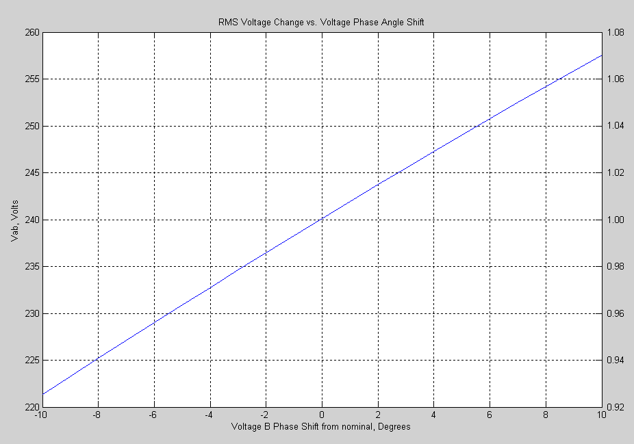
At zero degrees, Vac voltage magnitude is 240V, as expected. At 5 degrees shift, the graph shows 249V, as in the above example. As the phase shift increases, the voltage keeps increasing, roughly linearly for the range -10 to 10 degrees. The per-unit voltage equivalent is shown on the right Y-axis. For a 5 degree change, the voltage is almost 4% off. For the 7 degree shift in the actual data file, the voltage is 5.6% off.
The voltage change per degree of phase shift is nearly twice that of a regular delta with 120 degree nominals, making phase angle measurements much more important for unbalance in 4-wire deltas.
Conclusion
Voltage unbalance is important to measure in a 4-wire delta circuit due to the extra sensitivity to phase shifts, the virtually guaranteed load unbalanced in this type of system, and the fact that all 3-phase loads will be delta connected. Using neutral-referenced voltage measurements can give a misleadingly low unbalance reading. Although unbalance trends can be seen in the stripchart data, a true calculation for delta-connected loads requires voltage phase angle data. Calculations and an example from a real data file were shown, along with a sensitivity graph to gauge the effect of different phase shifts.
