Abstract
This white paper describes what a Flex CT is, how it works, and a brief history on its development. Details are given on how to use the Flex CT to get accurate current measurements with PMI’s power quality analyzers.
Although the Flex CT is often referred to as a current transformer it is really a Flexible Current Transducer, not a true current transformer. It is however a special type of current transducer that allows for use in areas where conventional current transformers may not easily go. The design of the Flex CT allows it to be wrapped around a conductor, rather than clamped with a rigid CT. The technical name for this type of current transducer is a Rogowski-Chattock coil, named after its inventors. Usually the Rogowski-Chattock coil is referred to as simply a Rogowski coil.
History of the Rogowski Coil
In the year 1887, Professor Chattock of Bristol University came up with the idea and described using a long flexible coil of wire that was wound around a piece of elongated Indian-rubber used as a magnetic transducer. In the year of 1912 Walter Rogowski and Steinhaus described a technique for measuring alternating current (AC) and/or high speed current pulses. The Rogowski coil is made up of a helical coil of wire wrapped on a rubber core with the lead from one end of the coil returning through the center of the coil to the other end, so that both terminals are at the same end of the coil assembly. Under normal use, the whole assembly is then wrapped around a conductor whose current is to be measured. Due to the voltage that is induced in the coil, which is proportional to the rate of change of the current in the conductor that is being measured, the output of the coil directly correlates to the current developed in the wire which it surrounds. The output is connected to integrator / preamp interface circuit; its electronics are then powered by the recorder it is attached to.
The voltage produced by a Rogowski coil is:
where A is the area of one of the small loops, N is the number of turns, and l = the circumference of the coil. is the rate of change of the current threading the loop.
This formula assumes the turns are evenly spaced and that these turns are small relative to the radius of the coil itself. At high frequencies, the Rogowski coil’s inductance will decrease its output. The inductance of a toroid is:
V·s/(A·m) is the magnetic constant, R is the major radius of the toroid, and a is its minor radius.
Because the voltage output is proportional to the derivative (rate of change) of the current waveform, the signal is conditioned by an integrating circuit. The hardware integrator recovers the original current waveform by undoing the differentiation effect of the coil pickup. The voltage signal from a Rogowski coil is very small (typically just tens of microvolts per amp of measured current), so amplification is also performed, often as part of the integration circuit. Special shielded wiring is used in PMI Flex CTs to minimize noise pickup due to the low signal levels. The extremely low output is the limiting factor in creating Flex CTs capable of measuring small currents, and at currents below 1A, iron core CTs become more attractive.
Effect of Coil Placement on Measurement Accuracy
As shown in Figure 1, Flex CT coil windings are very uniformly spaced to ensure the greatest accuracy possible. Using Ampere’s Law, a perfectly uniformed coil encircling a current allows the output not to be dependent on the path the coil takes round the current or on the position of the conductor within the loop. There is only one place on the coil that does not have a uniformly spaced winding: at the coils ends. There is a small gap at the connector junction. For the absolute best accuracy and least amount of induced error, avoid placing the coil’s connector close to the conductor whose current is being measured. It is best to have the connector at least 1.5 inches from the conductor that is being measured. Having said this, empirical data suggest that it is slightly more accurate when the coil is a uniformed distance from the conductor, in other words the conductor is exactly centered in the coil’s path, but this is only a slight difference, normally less than +/- 0.5%. In practice, it’s usually impossible to perfectly position a conductor in the center of a Rogowski coil; the next best alternative is to position it as far away from the Flex connector as possible. In addition, the Flex connector should also be positioned away from other adjacent conductors, to minimize stray current pickup.
Since the Flex CT is just a type current transducer, it follows the laws of physics including the right hand rule (Figure 2). The phase of the current to be measured depends on the direction the current is flowing through the conductor under measurement.
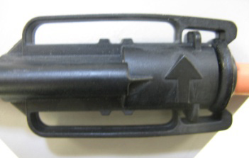
As shown in Figure 3, the Flex CT has an arrow on the end connector, so to get the proper current phase; it is a must that you have the arrow pointed toward the load’s direction.
The Flex CT is wrapped around a rubber core that responds electrically more like an air core rather than an iron core, which allows the Flex CT to have a very low inductance. This lower inductance enables the Flex CT to respond extremely fast to current spikes and fast current changes.
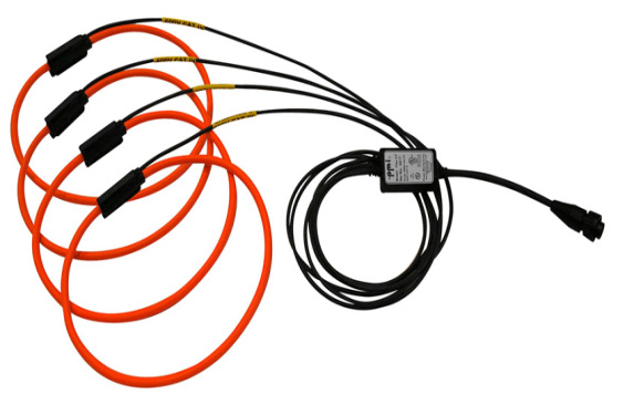
PMI has several models of Flex CTs (example shown in Figure 4) available for the Revolution, Vision, Eagle, ViP+, iVS-3 rev2, and the iVS-3/600P models. These 5,000 Amp max probes come in a variety of sizes to allow ease of use for current measurement of a wide variety of multiple conductor bundles. The standard sizes are 12″, 24″, 36″ and 48″. They come in 2, 3 and 4 channel models. The switchable ranges vary from 1 to 100 amps, 1 to 1000 amps, and 1 to 5,000 amps. They are designed to be powered from PMI’s recorders, so no external batteries are required. The coils are precision wrapped allowing linearity of +/- 0.05% and phase shift of less than or equal to +/- 1 degree at 50 or 60 Hz. The frequency range of the CT is from 8 Hz to 10 kHz. Overall accuracy is +/- 1% of full scale. All of PMI’s CTs are double insulated for a greater safety factor and have a working voltage of 600 volts AC to earth.
Conclusion
- A Flex CT is a special type of transducer called a Rogowski coil.
- A Flex CT is made up of a helical coil of wire wrapped on a rubber core with the lead from one end of the coil returning through the center of the coil to the other end, so both terminals are at the same end of the coil assembly.
- The Flex CT is a very accurate way of measuring alternating current and coil placement is not critical as long as the connector is placed at least 1.5 inches from any current-carrying conductors.
- The Flex CT allows the loop to be opened making it easy to wrap it around a live conductor without disturbing the power. It is much easier to use in high current applications than the typical iron-core transformers. In the iron-core models, there is a tendency for the magnetic field induced into the iron to make it very hard to unclamp. High currents can also saturate the iron-core transformers which under heavy current loads can cause them to heat up. In some designs the iron-core current transformers can allow high voltages to build up on their output terminals if a load is not attached. Also for an iron-core unit to measure current accurately, the ends of the clamp must be clean and free of debris.
- Due to the construction of the Flex CT, it is resistant to electromagnetic interference.
- The Flex CT allows a very large dynamic range of current to be measured due to its construction based on the Rogowski coil. It is very accurate in measuring currents from the very small to the very high current ranges.
- The Flex CT has a rubber core acting electrically as an air core instead of an iron core; it has a low inductance allowing it to be able to respond to extremely fast current changes and current spikes.
- Flex CTs will only measure alternating current and will not measure direct currents (DC) due to the physics of its design.
- Due to the design of the unique integrator / preamp circuit / calibration circuit, for correct current measurements on PMI recorders, only use PMI’s Flex CT.
- All PMI’s Flex CTs are double insulated to meet the 600 volt CAT IV safety requirements.
