Abstract
This white paper explores the feasibility of using a common measurement point between the source and load to determine the source of harmonics using only harmonic phase angle. Finding the source of significant harmonic distortion observed on a power system is an important part of being able to control the distortion. When harmonic distortion occurs in a distribution system, sometimes it is not apparent which customer is responsible for the power line distortion. At this point it is important to formulate a strategy of determining the origin of the power distortion in order to put in place a barrier to keep the distortion from propagating into the rest of the distribution system and on to other customers.
The main concern when monitoring harmonics in distribution systems are distortions of sinusoidal voltage and current waveforms. Harmonics can compromise the distribution system in many ways, such as excessive transformer heating, tripping circuit breakers, failed capacitor banks, trigger malfunction of electronic circuits, and communication issues due to RFI. Locating the source or origin of harmonic generation is a very important to any power distribution system so appropriate measures can be implemented to control the propagation of the distortions before the whole grid is affected.
The point where the utility source and customer loads meet is referred to as the point of common coupling or PCC. If possible it would be beneficial to implement a strategy using this common point, the PCC, to determine who is responsible for power system harmonic distortion, and who or what is causing the harmonic distortions.
Finding the Source of Harmonic Problems
In the past, one of the most common methods used to detect the source of harmonics was to determine the direction of the harmonic power flow. The side that contributed the largest harmonic distortion observed at the measurement point was considered to be the source. Although this makes some sense on the surface, in reality this method is unreliable, and can give contradictory results.
Both harmonics and the fundamental frequency cause energy to flow in a distribution system. The power in any harmonic is equal to the voltage of the harmonic times the current in the harmonic times the cosine of the phase angle or Ph = Vh x Ih x cos θh. If the capacitive reactance happens to become equal to the inductive reactance at one of the harmonic frequencies, resonances will occur. Resonances will exaggerate the effect and may give misleading results. Therefore it is important to consider the harmonics as a group, and place more emphasis on the odd harmonics, typically between the 3rd and 11th to reduce the effects of resonance at one given harmonic. It is natural to assume that the direction of the power flow is from the customer whose load is causing the harmonics back into the distribution system. However, this isn’t always the case.
The relative phase angle between the voltage and current for each harmonic, as measured at an intermediate point in the circuit, is affected by the line impedance, the impedance of all other loads in between, and also the specific nonlinear nature of the load itself. The frequency response of the distribution network and the nonlinear nature of the loads themselves vary with time and position on the network, making it very difficult to draw any conclusions from the power flow of any specific harmonic.
Even with everything else held constant, a change in the load itself can alter the power flow direction for some harmonics. The nonlinear nature of harmonic loads means that just about any phase relation can occur at individual harmonics. Even if the net power direction (mostly at 60Hz) is towards the load, individual harmonic power flow can be back to the utility, or towards the load. These flows are often more reactive than real power, and the real power direction at specific harmonics can be influenced more by the distribution network itself and the specific impedance characteristics of the load than the relative location of the power monitor to the load.
If the circuit consists mainly of a resistive load, the direction is reversed. The direction of the power is affected by the source magnitude and that of the reactive power by the phase angle.
To demonstrate the difficulty of finding the harmonic source direction using only harmonic power direction, an experiment was prepared using a light with a typical light dimmer as a nonlinear load. A setup diagram is shown in Figure 1. A typical light dimmer uses a switching technique that cuts up a sine wave after a certain threshold is reached past the zero crossing point. This level is usually set by a potentiometer used as a voltage divider feeding a semiconductor device called a TRIAC. Once a sufficient level is reached at some point on the sine wave to turn on the TRIAC, it conducts until the sine wave gets to the zero crossing point going negative and is turned off until the TRIAC is turned on again on the negative half of the sine wave. This change in duty cycle 120 times a second is what controls the light’s intensity. This process is very nonlinear, which makes for a load high in harmonic content. In the voltage and current capture waveforms in figures 2 through 5, it is easy to see at what points on the voltage waveform the light dimmer is triggered and is in the conductive phase of its operation. When the voltage is either high enough or low enough for conduction the current is allowed to flow to the load as shown in the current part of the waveform capture.

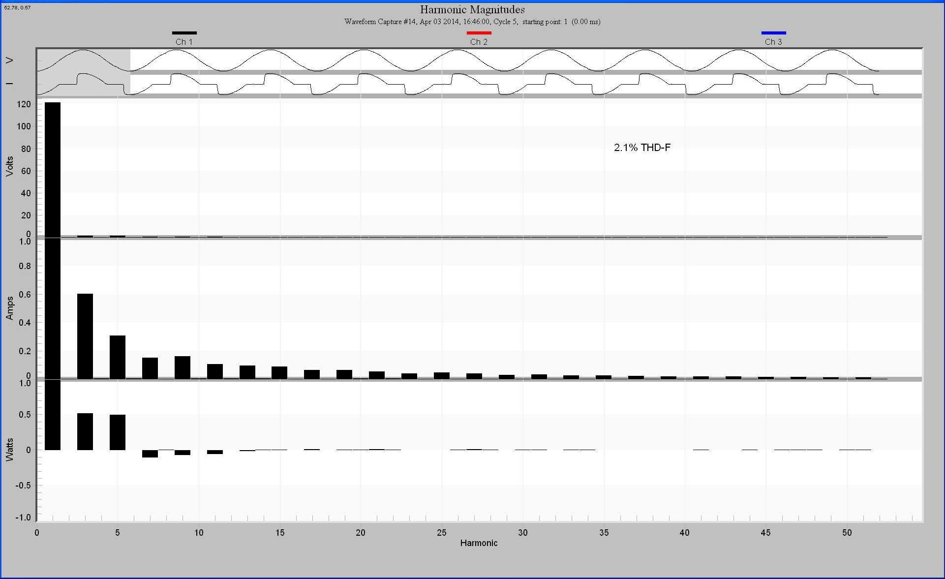
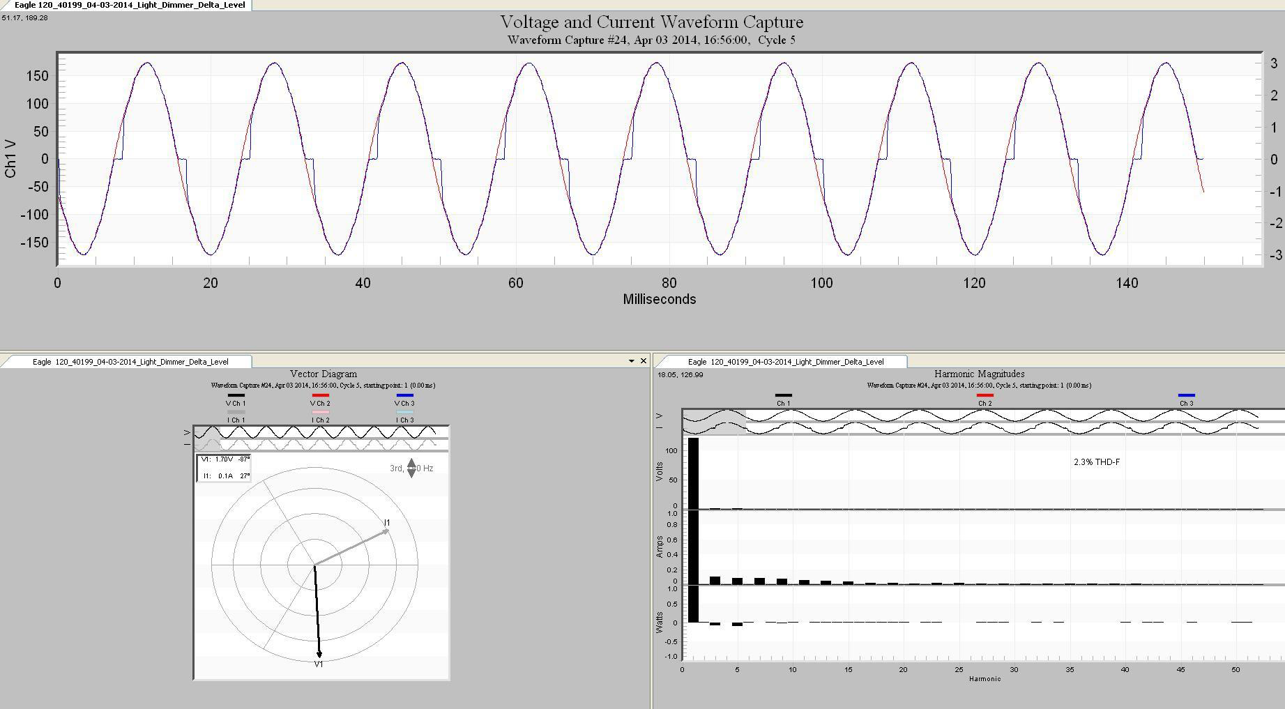
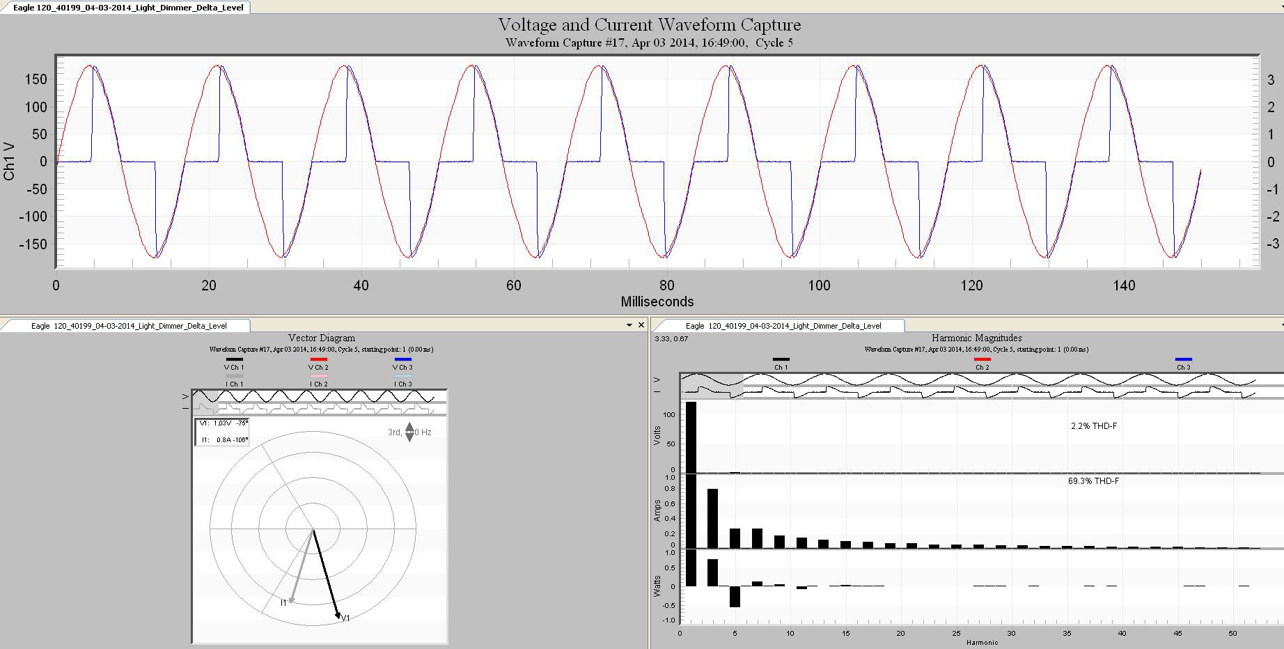
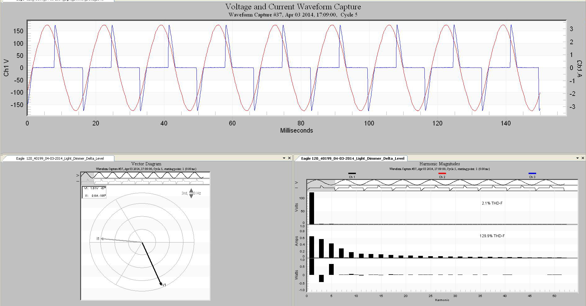
At different level settings the light dimmer would generate different harmonic profiles. Sometimes the 3rd harmonic was higher, and at other levels 5th dominated. This little experiment demonstrated that just by changing the light dimmers control slightly, the apparent direction of the harmonic power flow would reverse. Since there was a known power source and only one load, the true source of the harmonics are known beforehand which makes it much easier to analyze the validity of the method.
Conclusion
With measurements from only one position, using a point of common contact between the source and loads, it would be very difficult if not impossible to determine the source of harmonics based on phase angle. With a simple setup using a light dimmer used as a nonlinear load it is possible to show that the apparent direction of power flow in the harmonics does not indicate which direction the harmonics source is coming from. Here the power flow direction of the 3rd and 5th harmonic was made to vary to and from the load simply by changing the dimmer position. In each case, the dimmer was the source of the harmonics, so harmonic power flow cannot be a reliable indicator here. With a distribution system supplying multiple branch loads from a common contact point, it would not be possible to use this method to determine the source of the harmonics. It would then be necessary to implement another type of strategy to answer the question of true origin of the harmonic source.
