Dimmer switches for residential lighting applications have been available for decades. They are fairly ubiquitous in many homes and are often used for mood lighting and energy savings. The technology used in residential dimming applications is surprisingly complicated but it was originally designed to work with incandescent light bulbs. There are other types of lighting now commonly used in residential applications including halogen, fluorescent, compact fluorescent (CFL), gas discharge and LED (light-emitting diode). These different types of lighting have varying requirements for dimming that are not compatible across the board. For instance, while a typical dimmer switch purchased from a local hardware store will work with all incandescent and halogen lights, it probably will not work with fluorescent lights and it may or may not work in a satisfactory manner with LED lights. This whitepaper will discuss the methods used to dim incandescent lighting and why this is less effective and sometimes unusable with replacement LED bulbs.
Incandescent Dimming
The first dimmers were nothing more than a large variable resistor commonly known in this application as a rheostat. It accomplished the dimming function by forming a voltage divider with the bulb filament, resulting in a proportionally lower voltage seen by the bulb. This method would give effective control of the light output but with the downside of the dimmer having to dissipate the power not being used by the load, since the remaining 120V appeared across the rheostat. This severely limits the usage of a rheostat as a control mechanism for any significant power such as needed for AC voltage powered, residential lighting. Incandescent bulbs (which includes halogen bulbs) are purely resistive loads operating during the positive and negative phases of the AC sine wave. This is effectively equivalent to the RMS voltage being supplied to the light bulb. The waveform in Figure 1 shows the beginning of a rheostat controlled reduction in voltage. It is interesting to note that this would not result in any power savings or efficiency gains since the power not used by the load is being dissipated in the rheostat.
Typical residential dimmers are made with solid-state components (semiconductors) that can control the on/off periods of an AC waveform. This method also reduces the effective RMS voltage but without having to dissipate any significant power since the voltage is switched on and off rather than simply diverted to a rheostat. Figure 2 shows a waveform being controlled by a solid-state dimmer at approximately 30% of full output. Notice the extended off periods of the sine wave which results in a partial waveform with a reduced overall RMS value over the full 60 Hz cycle duration. This method of dimming does reduce power consumption and results in an efficiency gain.
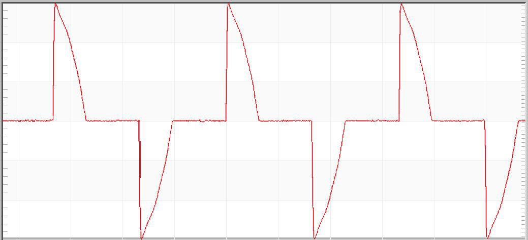
This technique is called phase dimming and it works well with incandescent lighting. Phase dimming can further be characterized as leading edge or trailing edge dimming depending on which partial phase of the waveform is being manipulated. The waveform in Figure 2 is an example of leading-edge phase dimming.
LED Dimming
Traditional phase dimming is not directly compatible with LED lighting. Using these dimmers with LEDs may or may not work acceptably. Oftentimes, it will be a trial and error process to get the right combination of LED bulbs and dimmer to work properly. Even then, the results will likely not compare favorably in comparison with incandescent bulbs. Even with LEDs that are marketed as “dimmable”, the functionality could still be impacted by reduced output range (especially at low levels), abrupt switching on or off instead of fading, pulsating light levels and/or noticeable flickering (again at the lower levels).
LED bulbs that are manufactured to replace incandescent bulbs must be powered via AC voltage. LEDs are semiconductor devices that operate with a constant DC current so the LED bulbs will have an integrated driver that uses a rectifying AC to DC power supply, with a constant current controller. The design of this power supply will determine how well the LED can be controlled via phase dimming.
The driver circuit must be able to operate with the reduced RMS voltage and still produce the required DC current while also limiting the current to the LED proportionally in order for it to be dimmed.
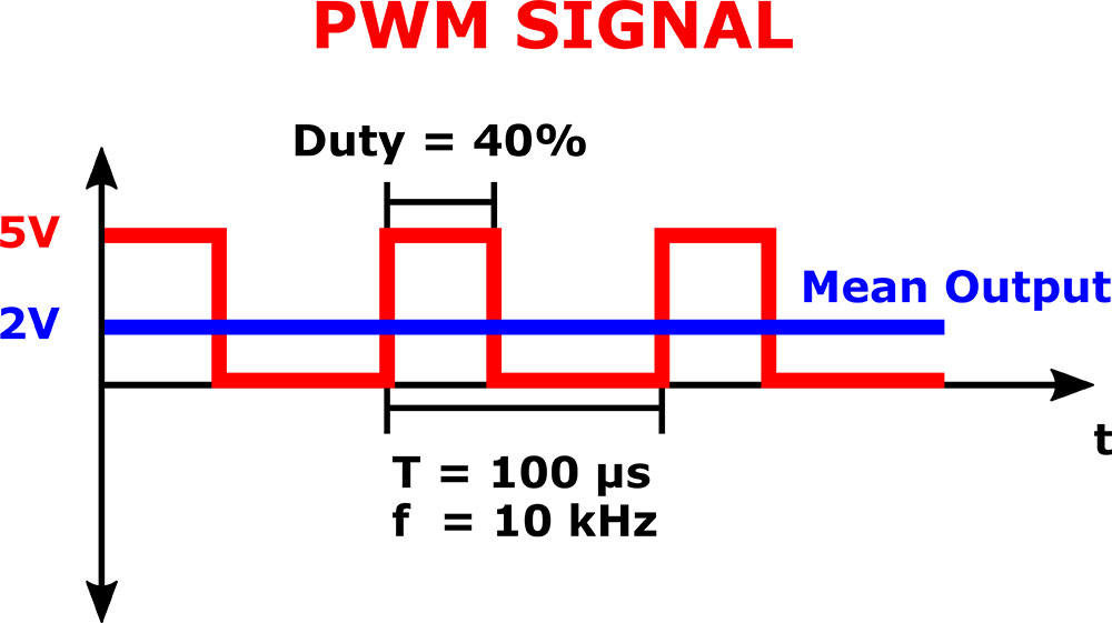
More precise control of an LED can be accomplished via a technique called pulse width modulation (PWM). PWM creates a steady stream of on/off pulses in the DC voltage driving the LED, resulting in a desired average current through the LED. A relatively high frequency of pulse stream is needed so that the individual on and off periods are not detectable by the human eye. The light output can be controlled by increasing or decreasing the length of the pulses with shorter on times being associated with a lower light level. The ratio of the on/off periods of the pulse is known as its duty cycle. Figure 3 shows a 5 volt signal being pulse width modulated 10,000 times per second with a 40% duty cycle to create an effective output equivalent to 2 volts. An LED attached to this output is actually receiving 5V and 0V switching 10,000 times per second so the light output is effectively reduced to 40% of full brightness (based on the duty cycle shown).
This type of control is usually accomplished using a microprocessor but can also be done via discrete components. LED bulbs using PWM control are usually associated with more expensive bulbs that have a means to remotely control the light via WiFi, Zigbee, Z-wave or other microprocessor based protocol. The bulb must be powered at all times even when the light is in the off state so the remote control system is ready to receive commands. These would not function properly when attached to the output of a traditional residential dimmer switch.
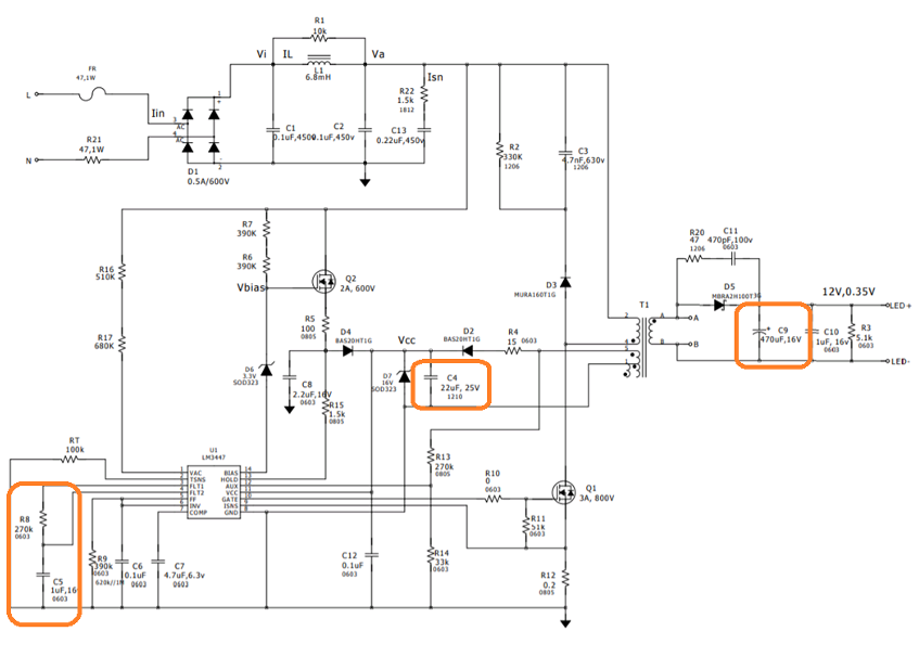
A typical schematic for an LED bulb design is shown in Figure 4. The utility AC voltage is rectified into a DC voltage bus. The voltage waveform or overall RMS voltage reduction from a traditional dimmer is not used directly in this design to produce a dimmer LED.
Instead, a high voltage transistor under control of the LED controller chip is pulsed with a specific PWM pattern to drive a constant current through the LED itself. Changes in LED brightness are produced by changing the PWM pattern to change the overall LED current. The controller chip detects a dimmer by sensing the change in voltage waveform, then altering the PWM pattern accordingly to dim the LED. The components outlined in orange are critical to the behavior of the bulb when voltage sags, oscillatory transients or other power line disturbances occur. These components also determine the sensitivity to dimmers and to false dimmer detection based on transients or powerline noise. Manufacturers often make different component choices based on cost, availability, etc. leading to dramatically different bulb behaviours and lifetimes even when using the same controller chip and architecture.
Conclusion
The introduction of higher efficiency methods of lighting has caused a previously standard method of dimming to become nearly obsolete. The common residential phase dimmer is slowly dying in usefulness as more types of incandescent light bulbs are phased out. The large installed base of traditional residential dimmers will continue to be useful only as long as compatible “dimmable” LED replacements are available. As mentioned earlier, even though an LED bulb is marketed as dimmable, it may not function adequately in all cases based on the type of dimmer in use.
