Abstract
Conservation Voltage Reduction (CVR) is a method for lowering peak energy demand by lowering the average system voltage during the peak periods. The Boomerang is designed to work with any CVR system, providing accurate voltage telemetry and triggering in real-time via an embedded, wireless, cellular data connection.
The CVR concept is to tightly regulate the voltage delivered to customers and to keep that voltage close to the regulatory minimum level. Instead of relying on a ±5% range, and assuming customers close to a regulator will be on the high end, and customers at the end of a line will be on the low end, a CVR system will attempt to keep all customers within 1 or 2% of the minimum. This greatly reduces the margin for voltage variations in the distribution system and requires more voltage regulators, voltage monitors, and real-time measurement and control to adjust equipment in response to load shifts over time.
A full CVR system is driven by a real-time modeling and decision-making software system. This system reads near-real time voltage and load data, feeds that data into a distribution model, and produces control operation decisions for voltage regulators, capacitor banks, and other distribution equipment as needed to maintain voltage regulation as per the CVR goals. Most CVR back-end systems interface with outside equipment through an existing SCADA system– all control commands and data measurements pass through the SCADA gateway. The CVR modeling and decision algorithms range from simple mappings between voltage regulators and monitoring points, to full modeling of all feeders, and numerical state estimation and load prediction.
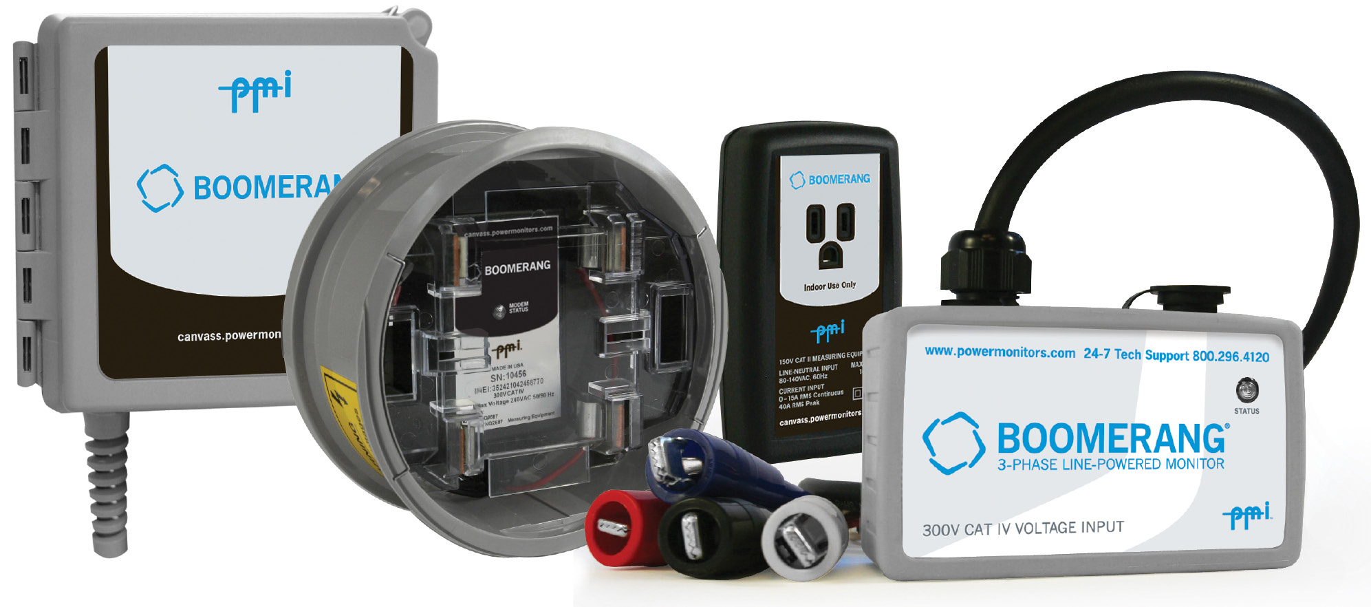
The Boomerang operates on the very edge of the CVR system– at the transformer secondary, measuring delivered voltage. CVR systems require near real-time voltage readings, and these should be electrically as close as possible to critical monitoring points. The toughest decision is where to monitor for residential locations– at the meter base or transformer secondary? Advantages for the meter base are that the service voltage drop is included, and this is the point where the regulatory minimum voltage applies. Advantages for the transformer secondary are that installation is less disruptive (no outage to the customer), and voltage readings are more representative of distribution voltage. The Boomerang is available in meter base and pole-mounted versions (and even a 120V plug-in version), so the choice should be based on system model requirements and measurement goals. These form factor options are shown in Figure 1.
For transformer secondary monitoring, fixed voltage offsets may be used to adjust for a typical or near-worst-case service voltage drop, or the drop may be modeled as part of the system model if the CVR program is that detailed. Sensitive locations or electrically representative sites may be selected for meter base monitoring, to characterize service voltage drops.
The Boomerang includes a full DNP3 interface, allowing polling for voltage readings by a SCADA system. With frequent polling (every few minutes, or even once a minute), this information is enough for a CVR system to operate. However, the most effective use of the Boomerang is through the triggered alert system. The Boomerang includes a sophisticated threshold and triggering system, fine-tuned for CVR systems. By making full use of the triggered Boomerang voltage alerts, polling can be minimized, and the Boomerangs can use a very low-rate cell data plan, mostly reporting by exception.
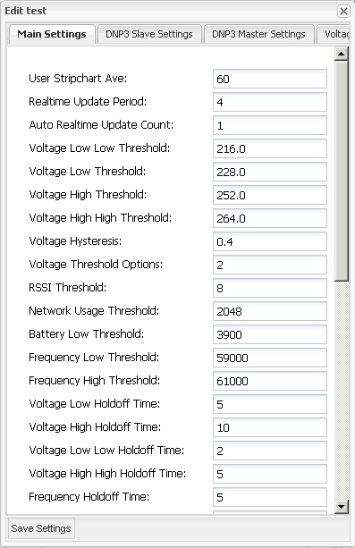
The Boomerang includes four voltage triggers: lowlow, low, high and highhigh. The lowlow and low triggers operate below the nominal, and fires if the voltage falls below them. The high and highhigh thresholds fire if the voltage rises above the nominal past the thresholds. An adjustable hysteresis is available to avoid chattering if the voltage is hovering right on a threshold. In addition, a minimum trigger time can be set so that the trigger condition must persist for a minimum time before the trigger actually fires. If the voltage returns to nominal before the minimum time expires, the trigger is not met, and a further crossing restarts the timer from zero.
The most important option for voltage triggering is the averaging window. The Boomerang measures raw RMS voltage with a 1 second RMS period. This raw measurement is usually too fast for a CVR system– the goal is to respond to changes in steady-state voltage, not short-term sags or dips. To smooth out sags and dips, an adjustable averaging window is used to produce an averaged voltage. Typically several minutes long, this sliding window is used to produce a new running average volts reading every second. This preserves the real-time aspect of the reading, while still utilizing an averaging window for smoother voltage values.
Typical settings for a CVR system (assuming a 120V basis) are 112V, 115V, 123V, and 125V for the lowlow, low, high, and highhigh values. The low and high thresholds can be used for switching decisions, and the lowlow and highhigh values for alerts based on outer limits of desirable voltage under CVR. A 0.4V hysteresis and 5-second minimum trigger time are effective at preventing nuisance triggers.
Care should be taken when setting the averaging window period. If set too fast, voltage regulators may adjust too often, or even before the system has finished responding to previous operations and settled to a new steady-state value. If set too slow, voltage adjustments may be delayed, leaving customers with low voltage for many minutes while the system slowly discovers the true line voltage. A value between 3 and 6 minutes is generally a good starting point.
The triggering mechanism can be used to control DNP3 unsolicited report by exception (URBE). With this enabled, the Boomerang can be polled on a much slower basis (e.g. once per hour or even several hours), relying on the Boomerang to report in as soon as a voltage threshold is crossed. This method can dramatically reduce cell data usage– polling once every 5 minutes can range from 5 to 15 MB/month, while URBE mode can be as little as 1 MB/month.
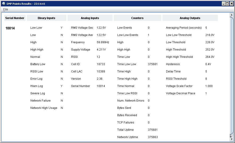
Both the fast one second RMS voltage and slower, averaged voltage reading are available through DNP3, so the CVR system (or SCADA data historian) may use either. Another option for both voltage readings is the precision, expressed as the number of decimal places. The Boomerang itself measures to the nearest 0.1V, designed to produce enough resolution to detect single tap changes in a typical voltage regulator or tap-changer. However, with a long averaging window, it’s possible for the exact same voltage reading to be returned several times in a row. Some SCADA systems are designed to assume a “stuck” sensor if the same reading is returned twice in a row, and take the sensor offline. To get around this “feature”, the Boomerang can be set to return two or three decimals of resolution. Although the Boomerang is only specified to 0.1V resolution, the extra two digits are helpful to avoid being declared “stuck” by a SCADA master. An adjustable scale factor may also be set in the Boomerang, to normalize all readings to a common basis (e.g. 120V), even if some are on 240V systems.
Another CVR-specific feature of the Boomerang is periodic URBE. Some CVR systems require more frequent voltage readings during certain periods– e.g. during peak demand windows, or after a voltage regulator has switched. Since most CVR systems are dependent on the SCADA system for data, it’s up to the SCADA system to poll when the CVR program needs data. However, most SCADA systems were not designed for the needs of CVR data collection and aren’t able to adjust polling cycles based on time of day or device operations. To get around the SCADA limitations, the Boomerang includes an automatic periodic URBE feature. If a voltage threshold is crossed, the Boomerang will send the normal DNP3 URBE, indicating a voltage excursion. This URBE will trigger a series of new URBEs on a periodic basis, for an adjustable time period. For example, the Boomerang could be set to generate a new URBE every 30 seconds for the next 15 minutes if a threshold is crossed. This data could pass through the SCADA system into the CVR program, thus meeting the CVR data requirement, without any extra polling from the SCADA master. This auto-periodic URBE corresponds to Burst mode when using the Boomerang with Canvass.
The Boomerang can also be configured to send periodic URBEs during a certain time window during the day. For example, if peak demand is from 2pm to 6pm, the Boomerang could send URBEs every 2 minutes during that window, and rely on much slower SCADA polling outside that interval. In addition to the voltage triggering, the Boomerang includes counters that can be used for basic voltage characterization. A counter is included for each voltage threshold, and each second that the voltage exceeds a threshold increments the counter. Over time, these counters give a good indication of the percent time spent within the nominal band, and outside that band. Collected in aggregate over all Boomerangs, a system-wide view of steady-state voltage level can be gathered, even if no SCADA historian is present, and no CVR data stored.
Conclusion
The Boomerang is a DNP3-enabled voltage telemetry device custom-created for CVR applications. With features designed to work around the limitations of existing SCADA systems, the Boomerang is flexible enough to meet the demanding requirements of real-time CVR systems, while minimizing cell traffic and telemetry costs.
