Abstract
In this White Paper I investigate the effect that a metal enclosure has on cell signal strength. A frequent question that we have is how can we get a cell signal out of a metal transformer enclosure without drilling and running wires out? Can a Cell Revolution along with its antenna be installed inside a metal enclosure and actually work? The answer is sometimes, it depends on several factors that I will cover in this paper.
For this white paper some simple experiments were performed in order to answer these questions and demonstrate the best approach for antenna placement inside a metal enclosure.
Understanding Antennas
First of all, it is important to understand that an antenna’s performance is a function of its environment. The antenna’s function is to launch and receive signals. The antenna is designed to provide a good 50 ohm resistive load to the modem at the proper operating frequency, allowing the RF to be launched in a predictable radiation pattern, and not reflected back into the modem. When the antenna is enclosed and the radiator is close to metal, the antenna may not provide the match the antenna’s manufacturer intended. In this case, instead of the modem seeing the 50 ohm load it was designed to see, the modem will see a more reactive load, similar to dealing with poor power factors in electric power distribution. Large metal objects near the antenna will tend to de-tune it, causing an impedance mismatch with the modem. By surrounding the antenna with metal, such as installing an antenna inside of a transformer enclosure, the enclosure and everything inside the enclosure can drastically effect the antennas’ operation making it very unpredictable.
It goes without saying that any prediction of the antennas’ radiation pattern is not valid when it is surrounded by a metal enclosure. The smaller the enclosure (and hence closer the metal walls are to the antenna), the larger the possible effect. Sometimes it is preferable to use a lower gain, lower-Q type antenna, due to a broader operational bandwidth making it a little harder to detune. However, while a very large, empty metal enclosure may not detune the antenna too much, a metal enclosure also presents a problem by reflecting RF instead of letting pass through, described in the next section.
Enclosures Leak RF
In theory, a perfectly sealed metal enclosure will block all electric fields from entering or existing the enclosure. Unless the enclosure is a sealed, RF-tight box with special sealed doors, such as with a screen room, RF will leak out to some degree. Even with a screen room there will be some (very small) leakage. Any RF leakage helps to let a cell signal out, and received RF from the cell tower in. Fortunately a typical electric power metal enclosure is far from RF-tight. The amount of RF leakage depends on the size and location of the gaps around the doors and other openings such for ventilation and wiring, in relation to the wavelength, phase and polarity of the RF signal involved and how electrically conductive and thick the material making up the enclosure is. Also, unless the power conductors are RF bypassed or filtered, the wires entering the enclosures can sometimes act as antennas by absorbing the RF on one side of the metal enclosure and reradiating the signal on the other side. This re-radiation by electric power conductors can result in RF leaks from the enclosure.
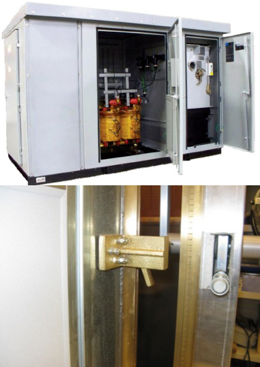
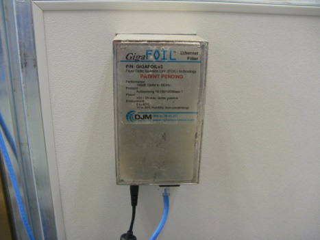
Notice in Figure 1 that there is no real RF seal on the transformer enclosure, as in Figure 2, a picture of a screen room door. Notice the rigid beryllium/copper construction around the screen room door, necessary to create a true gapless RF seal. Figure 3 shows a filter to block any RF from entering or leaving the screen room on Ethernet wiring. This type of filtering is not present on power conductors in an electrical enclosure, which allows RF to be absorbed by the conductors, and re-radiated outside the enclosure – another source of RF leakage that is advantageous in using a cell device inside the enclosure.
The basic rule of thumb is if a metal container has an opening smaller than 1/10 of a wavelength of the frequency of interest, the signal will not propagate very well through the hole. The wavelengths for cell phones are relatively short and can usually find its way out of most metal enclosures, however metal can and will reduce the signal strength significantly. At 850 and 1900 MHz a tenth of a wavelength would be 1.39″ and 0.62″ respectively. It would be very hard to find an electric power enclosure without a gap smaller than 0.62″ in any direction to completely eliminate all leakage in the cell bands. Most transformer enclosures are not specifically designed to eliminate radiation in the cell phone band, rather they provide a safety barrier.
If the power conductors that run in and out of the enclosure are also enclosed for some distance in metallic conduit or underground, this can reduce the ability for RF to be conducted out or re-radiated. PVC plastic piping may absorb some RF, but most will pass through and could then be reradiated.
Communication Range
To determine whether or not an internal modem will work depends on the specific location and situation of the enclosure and how close it is to a cell tower. The average sensitivity on the cell modems is somewhere between -104 to -107 dBm. The power output of the modems is around 23 dBm or 200 mW. The main factors that determine maximum range on a cell modem is the cell tower’s power, height, receive sensitivity, antenna gain, frequency, and terrain. The cell signal strength decays at a rate of the square of the distance between the transmitter and receiver. In dBs, the signal becomes 6 dBs weaker for each time the distance is doubled. If the cell modem is using the higher US PCS frequency in the 1900 MHz band, there will be slightly higher attenuation per distance compared to 850 MHz, US cellular frequencies due to the higher frequency has a shorter wavelength. This small amount of loss on the higher frequency is usually made up by slightly higher antenna gain that can be achieved by a similar sized antenna.
Internally Generated Noise in the Enclosure
Another concern is that the noise generated internally can affect the communication range. If there is equipment in the enclosure that generates noise in the 850 MHz or 1900 MHz cell band, this can reduce the communication range by covering up the desired signal. The metal enclosure will trap much of the radiated noise inside, and the close proximity to the antenna exacerbates this effect even further. Although most distribution transformers will not contain noise-generating devices (or RF noise conducted into the power cabling), some Motor Control Center or Variable Frequency Drive enclosures, etc. with high power switching devices or noisy electronics could add RF noise. In this case, with all else being equal, choose an enclosure with as little potential for RF noise as possible. For example, to monitor a large VFD motor, putting a Revolution in the subpanel or transformer that feeds the drive may be better than in the drive controller box itself.
The Experiment
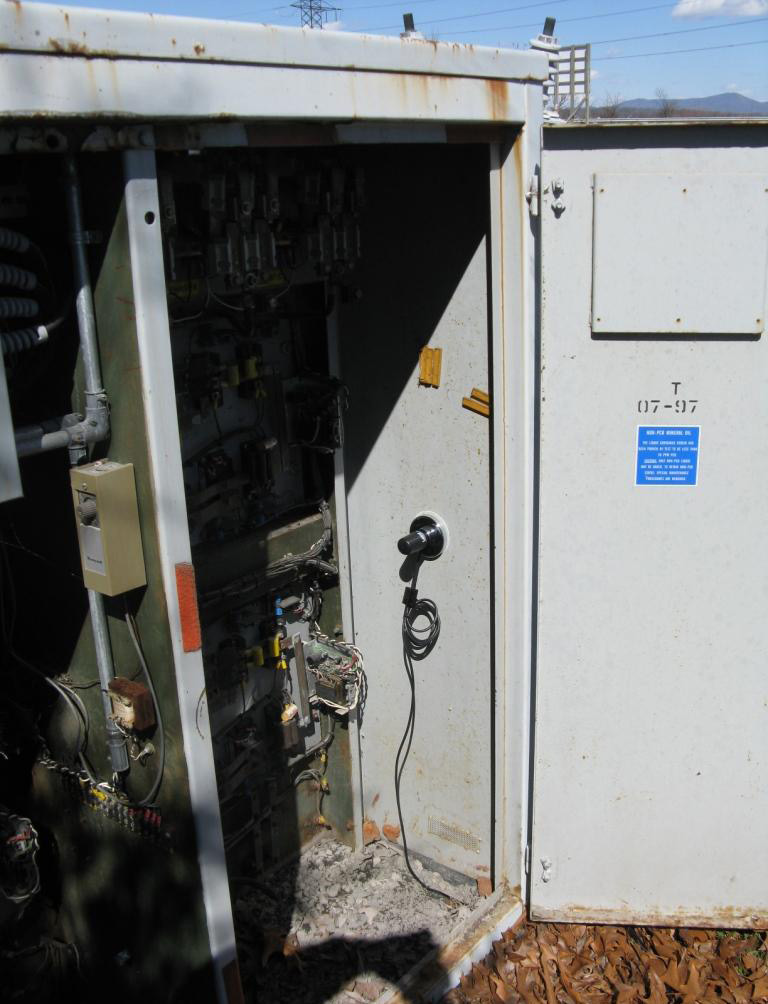
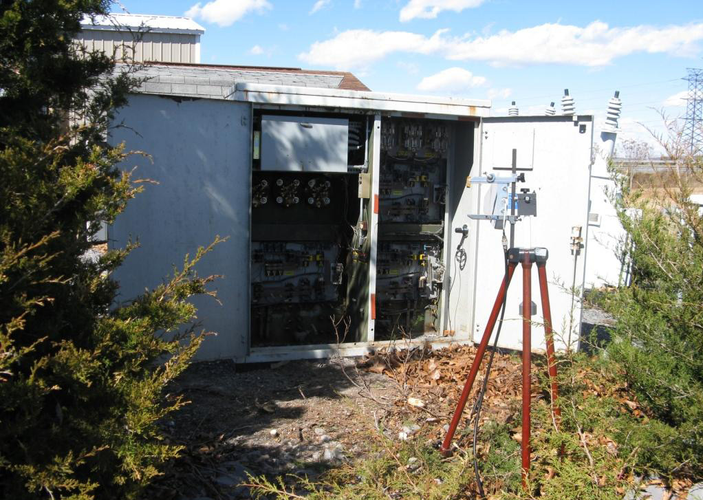
In this experiment, I wanted to test the shielding integrity of a typical transformer type enclosure. In order to do this I found a small hole at the bottom of the enclosure that I could pass the coax through and installed the Phantom type antenna inside for sweep purposes. The equipment used for sweeping the enclosure was a portable Rohde & Schwarz FSH6 Spectrum Analyzer used in the tracking generator mode along with an Antenna Factor ANT-DBI-LP-RM-01N Log Periodic antenna, power amplifier and Laird Phantom cell antenna. I also used the FSH-Z2 VSWR bridge and power divider to make return loss measurements on the Phantom antenna inside the enclosure. The details of the Phantom antenna can be found in the whitepaper Using the Cell Revolution Antenna Kit.
The first task was to check the return loss / VSWR of the antenna on the bands of interest with the door closed to see how the enclosure would affect the antenna match (i.e. how much the antenna is detuned).
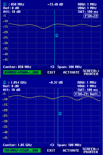
When the door is closed, the Phantom antenna experiences return loss in the US Cellular band and US PCS band, as shown in Figure 5. In Figure 6, the Phantom test antenna inside the enclosure against the metal wall used. In Figure 7, the Phantom experiences return loss in the US cellular band and in the US PCS band, even when it is attached to the metal wall, as illustrated in Figure 6.
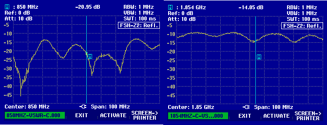
The above shows the return loss of the Phantom antenna next to the enclosure’s wall with the door closed as in picture in Figure 6.
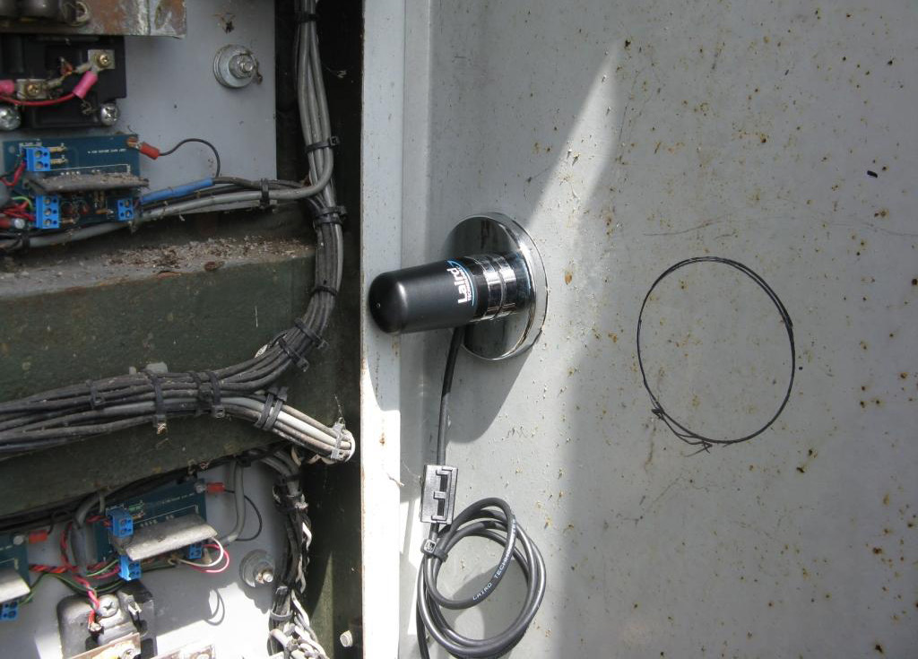
The return loss data collected on the Phantom indicated a good impedance match on both bands, even when the antenna is placed inside the enclosure with the door closed. Return loss is related to VSWR. The lower the return loss becomes, the better the match. Notice in the picture of Figure 4 that the antenna is placed away from metal as much as possible. Now note how the antenna is mounted in Figure 6, next to the metal wall. The antenna’s match is degraded from -20.95 dB return loss to -13.4 dB on 850 MHz. On 1.854 GHz return loss was degraded from -14.05 dB to only -8.37 dB. The better the match is between the modem and antenna, the better the energy transfer, thus the range. It is very important to not place the antenna against a metal wall as in Figure 6 and keep the antenna away from any metal as much as possible.
The modem would transmit on the US Cellular band between 824 to 849 MHz and receive from 869 to 894 MHz. Worst case return loss in the transmit band would be -15 dB and -13 dB on receive with the properly placed antenna. On the higher US PCS band where the transmit band would be 1850 to 1910 and receive from 1930 MHz to 1990 MHz the worst case return loss with the properly placed antenna was -10 dB on both the receive and transmit part of the band.
After verifying that the antenna’s match was good with the Phantom’s antenna placement, I preceded to do a frequency sweep of the system. A sweep will show how much signal attenuation is caused by the enclosure over each frequency band.
I initially hooked the sweep output up to the antenna inside the enclosure and the input up to a Log Periodic antenna spaced at about 15 feet, as shown in Figure 8. With the door closed, the sweeps noise floor was too high to actually measure the attenuation, so I moved the antenna in to 6 feet. This improved the response; however I needed to add an amplifier to the sweeps output to raise the signal from the noise floor to observe the pass band and to make good measurements.
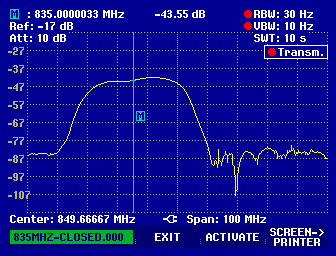
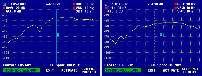
In Figure 9, the first screen shot is with sweep adjusted so to have the reference at close to the top of the screen with the door open. The second screen shot is when the door was closed to 6 inches and the last screen shot is with the door closed and shut. Above screen shots in Figure 9 are in the US Cellular Band, and below, in Figure 10, is in the US PCS Band.
By taking the difference between the open door condition and closed door condition, the loss due to the shielding attenuation can be determined. Rounding the numbers to the closest dB, at 850 MHz our enclosure has 25 dB worth of loss and 24 dB of loss at 1.854 GHz. The enclosure has much less attenuation with the door opened only 6″.
Conclusion
In general, a metal enclosure is going to attenuate a cellular signal. The amount varies greatly depending on the variables of each individual situation and location coming with its own unique set of variables. In our case the attenuation was about 24 to 25 dB.
Free space path loss to a distant receiver occurs with all electromagnetic signals. This loss causes the received signal strength to decay at a rate proportional to the square of the distance between the transmitter and receiver. Since cell towers and terrain vary, it is hard to calculate a true value for propagation range; however, an enclosure attenuation of 24 dB as in our experiment would reduce the range by 93.75% of the range without the attenuation. To put another way, 24 dBs of attenuation, due to shielding, reduces the range down to 6.25% of the theoretical range without the attenuation.
Another way to understand a 24 dB reduction is to equate it to cell phone signal strength as represented by signal bars. A typical cell phone indicates received signal strength as follows:
| Bars | dBm |
|---|---|
| 5 bars | -75 or more |
| 4 bars | -83 to -74 |
| 3 bars | -95 to -82 |
| 2 bars | -105 to -94 |
| 1 bar | -110 to -104 |
| 0 bars | -111 or less |
A 24 dB reduction would take a -75 dBm 5 bar signal down to -99 dBm, or in the middle of the 2 bar level. The signal outside the enclosure would have to be a strong 3 bar, or better 4 or 5 bars to get at least 1 bar inside the tested enclosure.
Some tips for maximizing the performance inside a metallic enclosure:
- A larger metallic enclosure is generally better – more likely to have larger gaps, and allows for more space between the antenna and other metal.
- An enclosure with plastic pipe instead of metal conduit is better.
- Try to locate the antenna as far as possible from any metal inside the enclosure, or from the walls or door. Putting the antenna near a small opening may be counterproductive, if it detunes the antenna. RF will reflect many times inside, and find its way out if there are gaps.
- If possible choose an enclosure without potentially noisy electronics.
If the enclosure is close to a cell tower, this experiment suggests that it can be feasible to locate the antenna inside the enclosure and still establish reliable contact. If the enclosure is at a remote location more than a few miles away from the nearest cell tower, or in hilly terrain, not line of sight with the tower, it would be unlikely to have a high probability of dependable communication. The position and polarity of the antenna inside the enclosure could be optimized to have a better connection. Since there are so many variables from enclosure to enclosure the optimum antenna position inside the enclosure will vary and may involve some trial and error to get the best performance. Having the antennas whip or radiation element mounted as far away from metal or a known noise source inside the enclosure is a good place to start. Sometimes moving the antenna a little can reduce the reflections causing the standing wave to be lowered and the modem to actually increase the output which could enhance the range. When mounting antennas inside the enclosure it is important to remember safety first and never take risks of mounting the antenna where it may come in contact with high voltages.
