Introduction
Electric utilities, in their mission to deliver safe and reliable electric power to the community, are regularly faced with a problem of efficiency caused by phase-shifted voltage and current waveforms. Traditionally, loads tend to lean inductive, due to the prevalence of transformers and motors. As the inductive loads introduce more 60 Hz phase shift between voltage and current, a larger proportion of the energy is wasted by transferring reactive power.
Power factor is a commonly used measure of the alignment between voltage and current waveforms. Capacitor banks are an important tool used by utilities to control power factor by compensating for the inductive nature of loads. They are increasing used instead for voltage regulation, since adjusting the reactive power flow also produces an RMS voltage shift due to changing losses through the distribution conductors.
This paper describes a three-part method to recognize these capacitor bank switch events within a power quality recording based on this effect, and presents a real world example. This method is important because it helps utilities recognize events within their system so that they can respond accordingly.
Method
Recognition of a capacitor bank switch relies on three key factors. The first factor is the presence of an oscillatory transient. This factor comes from the interaction between the inductance of the transmission line with the capacitor in the bank sending energy back and forth in a LC circuit. The frequency of this transient is usually significantly faster than the 60 Hz line, mostly in the 500 Hz – 5 kHz range. This ring frequency is determined by:

L is the effective line inductance and C is the capacitance in the capacitor bank plus any stray parasitic capacitance in the area. For example, if I plug in ordinary values of L = 1mH and C = 100uF, then:

The second factor is a step change in RMS voltage either up or down. This stems from their primary purpose: power factor correction. With power factor correction, the goal is to shrink the phase angle between the voltage and the current waveforms so that a larger portion of the energy generated goes to useful customer loads and a smaller portion is lost to heat. The voltage at the customer load can be approximated as:

Within, Vsource is the voltage measured at the substation and Iline and Zline are the transmission line current and impedance, all of which are complex phasors. When this correction takes place, the complex part of the line impedance is reduced and the real power increases based on the angle in the power triangle. Switching in a capacitor bank of size Qc reduces the reactive part of Iline by:

This lowers the voltage drop along the line and boosts the voltage observed at the load point.
The third factor is that the step change in RMS current must be small, <5% or 10% of its original value. When a cap bank switches, it does not have anything to do with the customer load, so the current should only change a little bit in response to the voltage change. This factor is included to rule out the possibility of a customer load turning off or on suddenly, causing a large change in current and potentially a slight voltage drop.
If the customer current is the cause for the disturbance observed, then the current observed will have to change much more than if a switching capacitor bank is the cause. The slight behavior of the current will depend on the overall nature of the customer load.
If the customer load is generally resistive, then the current will rise with the rising voltage and fall with the falling voltage in accordance with Ohm’s law. If, on the other hand, if the customer load is generally constant power, such as an AC-DC power converter, then the current will generally act inversely to the voltage so that the power drawn remains constant.
This triad of clues is indicative of a switch event but it is not definitive. It is possible that these systems can be heavily damped or filtered to the point that the ringing behavior is obscured and it looks like an impulsive transient. It is possible that a switch event occurs at the same time an unrelated customer load suddenly turns off, thus obscuring the third factor.
Example
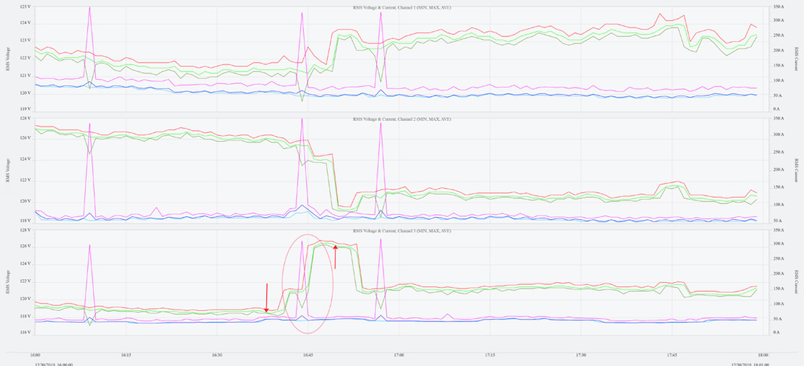
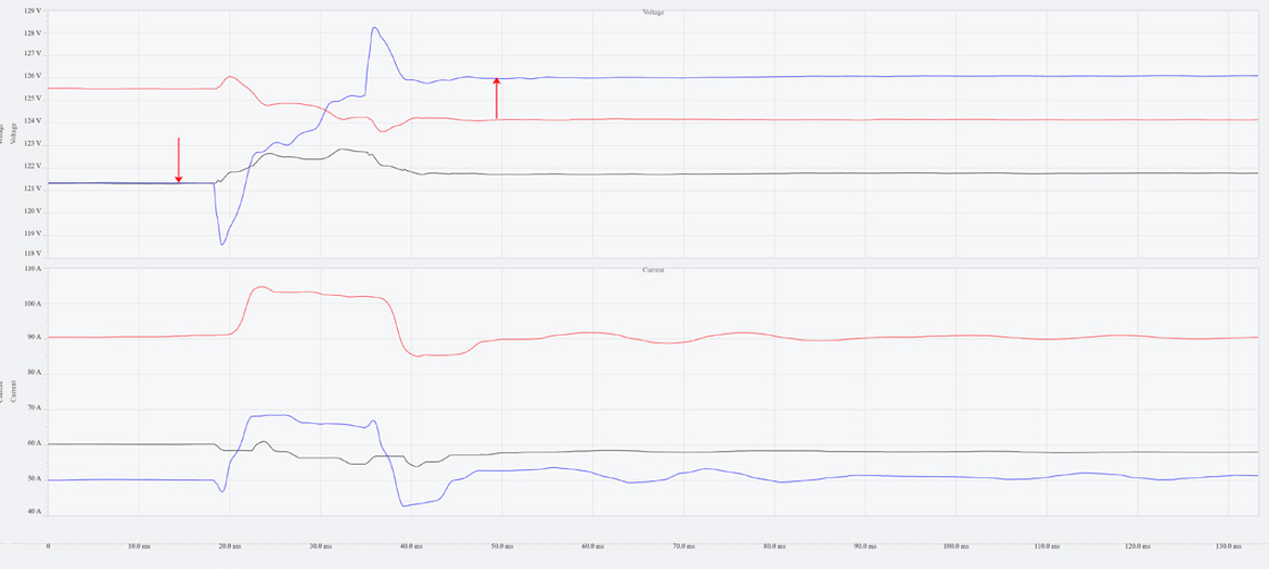
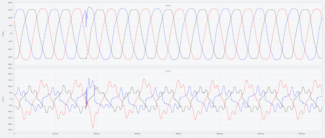
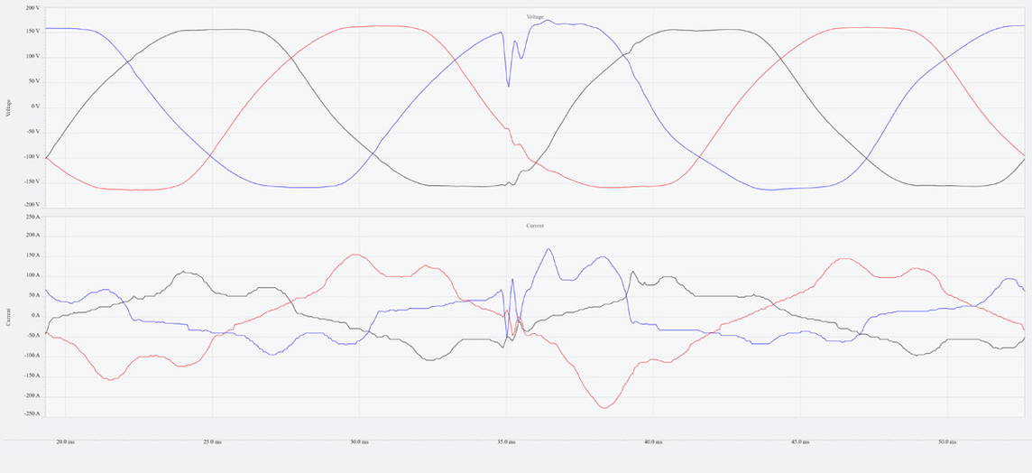
To illustrate this approach, consider the following real-world recording from a Power Monitors recording. Figures 1-4 show an example waveform of a capacitor bank switch event. The first factor, i.e. an oscillatory transient, is observed in figures 3 and 4. This transient has a roughly 2 kHz period and quickly decays within about 3ms. Figures 1 and 2 show the RMS voltage and current plots for this event, where figure 1 shows 2 hours around the event and figure 2 shows about 130ms. Both graphs demonstrate a large rapid step change in channel 3 voltage RMS while channel 3 RMS current is not significantly affected.
Conclusion
When looking at a power quality recording file, if an event shows an oscillatory transient combined with a step change in RMS voltage but not a significant change in RMS current, then that is likely a capacitor bank switch event. This method provides utilities with a good first pass visual test for a common occurrence within electrical systems. This is not meant to be a perfect method and it is certainly possible for some types of high impedance faults to mimic these behaviors and be falsely classified as a capacitor bank switch. As smart technologies continue to advance, methods of characterizing and analyzing power signals will become increasingly applicable.
