Abstract
Harmonic distortion is a broad, complex power quality issue with significant economic impacts for electric utilities and end users. Distorted current waveforms from end-user loads create excessive heating for utility transformers and capacitor banks, leading to premature equipment failures. Distorted utility voltage can cause customer equipment misoperation or damage, reduce motor performance, and cause benign loads to draw harmonic currents. An overview of harmonics and power quality is given here.
What Is Harmonic Distortion?
The ideal utility voltage waveform is a mathematically pure 60 Hz sine wave (Figure 1, red trace). This is the waveform produced naturally from traditional rotating electromechanical generation. The AC sine waveform combined with 3 phase delivery has many useful properties for sending electrical power efficiently over long distances. A consequence of the fundamental similarity between motors and generators: the 3 phase sinusoidal generator output is ideal for delivering constant power to AC motor.
Before the advent of electronic loads, the electric distribution system was well matched to customer load characteristics. Most large loads were linear — simple inductive AC motors, or resistive lighting and heating. The rise of modern electronics introduced switched-mode power supplies (SMPS), bringing many advantages to the end-user, but harmonic distortion to the grid. Variable Frequency Drives (VFDs) have largely replaced simpler motor starter and control systems, and from a utility perspective the inductive but linear motor current is replaced with a harmonic-rich waveform.
Steady-state waveform distortion is any consistent deviation from the ideal 60 Hz sine wave. “Harmonics” are simply sine waves whose frequencies are whole multiples of 60 Hz – e.g. a 180 Hz sine wave is the 3rd harmonic. Although distorted waveforms aren’t usually generated by a physical production and mixing of specific harmonics, it’s mathematically convenient to analyze a waveform as if they were. Much like breaking down a number into prime factors (e.g. 84 = 2x2x3x7), any complex, distorted waveform can be broken down into a unique combination of specific harmonics. This harmonic breakdown is often useful for tracking down root causes, and also for specifying mitigation hardware.
Steady-State vs. Transient Distortion
It’s important to distinguish steady state harmonic distortion from other power quality distortions and disturbances. Harmonic waveform distortion is consistent from 60 Hz cycle to cycle (see blue trace in Figure 1). Many harmonic problems stem from increased heating (due to several inefficiencies that worsen with increased frequency). The thermal mass of utility hardware is high compared to the heating from just a few 60 Hz cycle – it takes a sustained increase over many minutes (or tens of minutes) to make an appreciable difference. Although equipment lifetime may be drastically shortened with excessive heat loading, it may still be years of steady-state loading before an abrupt failure occurs.
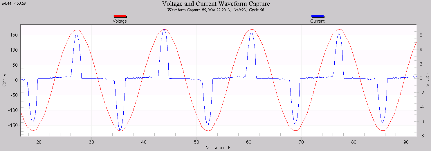
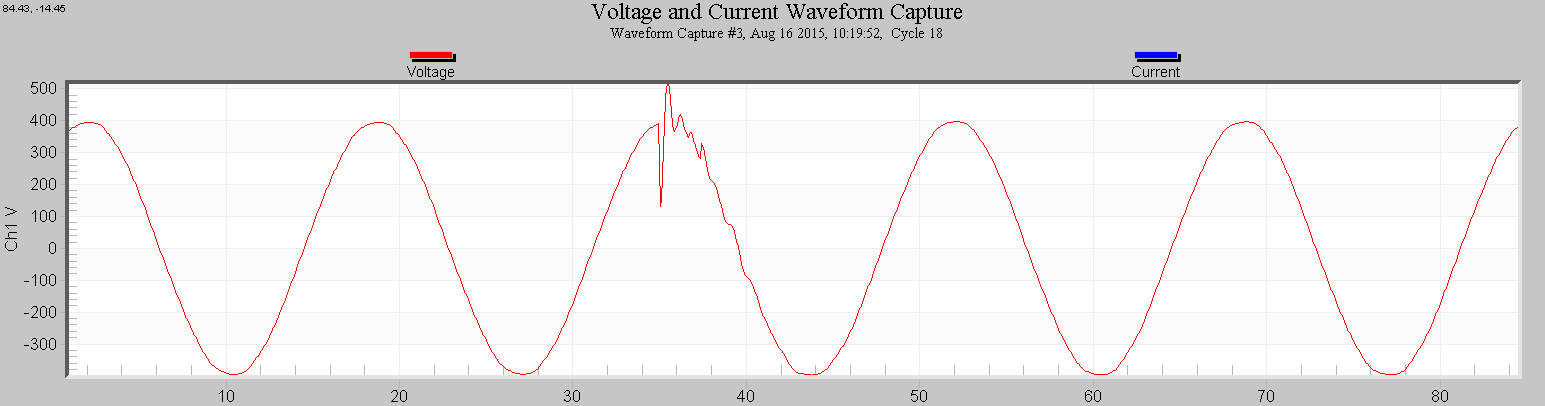
Figure 2 shows a common event that’s not a harmonic problem. This is an oscillatory transient, often caused by a utility switching event. Although the disturbance is composed of higher frequency sine waves, and can even be analyzed with harmonic tools, this is not a steady-state distortion. The effect is limited to just a single cycle, which is not long enough to increase heating in equipment, affect line losses, etc. For more detail on this distinction, see Steady-State vs. Transient Harmonic.
Although harmonics are a steady-state problem, the symptoms may present as discrete events. An abrupt transformer failure is obviously a one-time event, but severe unanticipated transformer loading can increase load sensitivity to voltage sag events. Waveform distortion that’s not well tolerated by intelligent loads such as VFDs may result in equipment shutdown on an intermittent basis as harmonic levels fluctuate, or when harmonics combine with other PQ events.
Relationship Between Voltage (Utility) and Current (Customer) Distortion
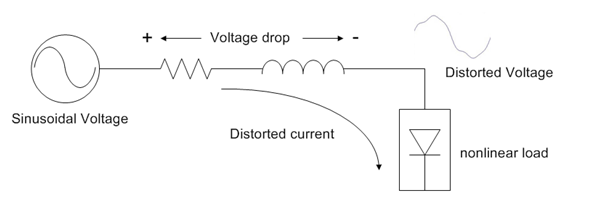
The physics of the electrical network tie the utility voltage and customer load distortion together. If there were no loads on the utility network, the voltage throughout the system would be a nearly perfect undistorted 60 Hz sine wave. Customer loads attached to the network draw current. This current flow through the network causes voltage drop across transformers, connection points, spans of wire, etc. as per Ohm’s law (voltage drop = current times resistance). If the current waveform is distorted (as produced by many modern loads), the voltage drop will also be distorted. This relationship is shown in Figure 3.
There are several important points that stem from Figure 3:
- Voltage harmonics stem from harmonic currents from nonlinear customer loads
- Voltage harmonics caused by one customer are seen by all others downstream
- A utility may reduce harmonic voltage by reducing the resistance along the feeder – larger wire, transformers, etc. but has no control over customer loads
In theory, a utility could reduce harmonic voltages to near zero by upsizing all wire, transformers, etc. until their resistance was negligible. Of course this isn’t practical, and some engineering compromise must be made between reasonable utility infrastructure (whose cost must be borne by all customers) and well-behaved customer loads. The challenge of reducing harmonic voltages is even more complex when one customer’s harmonic currents are causing problematic harmonic voltage for another customer.
Problems Caused by Harmonics
The most common problem stemming from harmonics is excessive heating. Transformers are typically the most impacted equipment for harmonic heating, due to internal losses that increase very quickly with frequency. For example, 1 amp of current at the 5th harmonic (300 Hz) produces 5² = 25 times the heating compared to 1 amp at 60 Hz. Harmonics don’t affect the RMS value nearly as much, so a transformer may technically be within its nameplate VA rating with a certain load just considering RMS voltage and current, but actually far above its physical limits if the current harmonics are high. Abrupt transformer failure may be the first sign of high harmonic content.
Certain harmonics (known as “triplens”) can lead to unexpectedly high RMS currents. Normally 3 phase loads are balanced such that the neutral conductor carries much less current than the phase conductors, due to 3 phase cancellation. This cancellation holds for harmonics, except for triplens (odd multiples of the 3rd harmonic – 3rd, 9th, 15th, etc.) Current at these harmonics add rather than cancel. This current addition can create unexpectedly high current in the neutral, exacerbated by the historic practice of undersizing neutrals. Building fires have occurred from this specific condition. In addition, system protection relays or breakers may be fooled by unexpected neutral currents, resulting in nuisance breaker trips. Triplen currents may also circulate in some transformer configurations, adding to their heat load. High neutral current also results in high neutral voltage, presenting problems for sensitive loads.
Certain harmonics (known as “negative sequence”, such as the 5th and 11th) are of particular concern for motors. Negative sequence harmonic voltage applied to a 3 phase motor will cause reverse torque, acting against the 60 Hz fundamental. An extra 60 Hz current is drawn to compensate, again increasing heat load on the motor and distribution transformer (motor losses also increase as the harmonic number increases).
Harmonic currents also decrease utility efficiency. Power factor, the traditional measure of utility efficiency in delivering energy to loads, is adversely affected by harmonic currents. Current at higher harmonics delivers little to no billable power, but must be carried by the utility infrastructure. The true power factor can be separated into the traditional 60 Hz phase shift (displacement power factor), and inefficiency solely due to harmonics (distortion power factor). Although they combine to a single power factor measurement, the root causes and mitigation strategies are much different (see our white paper “Understanding How Harmonics Affect Power Factor” for more detail).
Harmonics Mitigation
Harmonics are best mitigated by reducing or removing the distorted current as close as possible to the source load. The simplest filter is a line reactor, essentially a 3 phase inductor in series with the load. This presents a higher impedance to current harmonics. The higher impedance helps block harmonic currents from flowing back through the network. The load itself sees even more voltage distortion from the extra impedance but in many cases this is not a problem for the offending load itself. There are tables to help size a line reactor based on VFD motor and drive type. An isolation transformer is a 1:1 ratio transformer that can provide the same reduction as a line reactor.
If the customer load is high in harmonics but within acceptable industry limits, a utility may need to de-rate or upsize the distribution transformer. K-rated transformers are designed for the extra heating of harmonic currents. The K-factor of the load is used to selected the required K rating of the new transformer, or to de-rate the existing transformer. For more on transformer K-factor, see Tips on Transformer K-Factor. Note that a K-rated transformer doesn’t actually reduce harmonic current levels.
Filters may be installed by customers to block specific harmonics so the current does not reach the distribution transformer (or customer transformers within a large facility). Passive networks are formed with internal inductors and capacitors and tuned to specific harmonics. An active filter is similar to a static VAR compensator, and is able to dynamically reduce harmonic currents by injection cancellation current into the system.
Measuring Harmonics
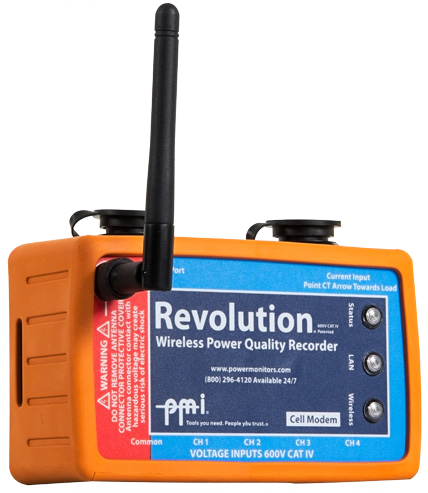
Harmonic measurements are relatively complex compared to RMS voltage and current, real power, and other traditional loading metrics. Continuous logging of each harmonic requires an advanced power quality recorder combined with a large amount of on-board memory, or ability to stream data to a cloud-based system. In addition to specific harmonic levels, Total Harmonic Distortion (a measure of overall voltage or current distortion) and Total Demand Distortion (a measure of current harmonic loading relative to the service size) are important to record for analysis. The Revolution PQ recorder (Figure 4) measures harmonics to IEC 61000-4-7. Recording Harmonics gives some recommendations for configuring the Revolution for this application. In most situations, a minimum one week recording is needed to comply with harmonic monitoring standards.
Harmonic Standards
The IEC 61000-4-7 standard gives a precise mechanism for computing harmonics, but this standard is more applicable to PQ equipment manufacturers than end users. IEEE 519-2014 is an excellent resource for best practices conducting a harmonic investigation, and also gives recommended limits for both utilities and customers.
A key point in IEEE 519 is the partnership between the electric utility and end-users. Utilities are responsible for voltage quality as delivered to customers at the service entrance, but distorted customer load current (which the utility has no control over) is the root source of voltage distortion. Utilities should abide by the voltage harmonic limits presented in IEEE 519, but is only practicable if customer loads also abide by the recommended current harmonic limits. The engineering compromise between excessive utility infrastructure and reasonable customer loads is contained in IEEE 519.
Conclusion
Although distortion begins with harmonic currents drawn by end user loads, the physics of the electrical network means that the utility voltage waveform is also distorted. This has significant consequences for both utilities and customers. Harmonics are a complex issue requiring coordination between utilities and end users to achieve acceptable power quality while maintaining reasonable infrastructure costs.
