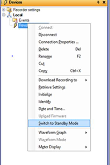
1. If possible, use ProVision to place the recorder in standby mode to stop recording
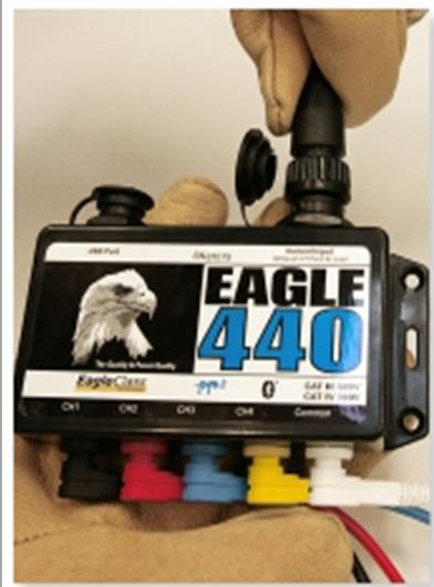
2. Disconnect the CTs from the recorder then remove them from the conductors
3. Remove the common (white) voltage lead from the recorder, and then remove the voltage clip from the conductor
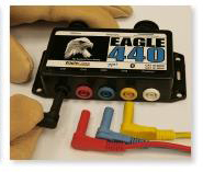
4. Remove the connected voltage leads from Channels 4 (yellow), 3 (blue), 2 (red), and 1 (black) from the conductors, then remove the leads from the recorder
