• Skip to primary navigation
  • Skip to main content

PMI

  • Home
  • Products
  • Library
    • Videos
      • All
      • Bolt Quality Tests
      • Promotional Videos
      • Support Videos
      • Power Quality Decoded
    • White Papers
      • All
      • Artificial Intelligence
      • Case Studies
      • Communications
        • All Communications
        • Cellular Communications
        • General Communications
      • Distributed Generation
      • IEEE Standards
      • Power Quality
        • All Power Quality
        • Analyzing Waveforms
        • Flicker
        • PQ Data Analysis
        • PQ Theory
      • Products
        • All Products
        • Boomerang
        • Boomerang SCADA
        • Box Recorder
        • Canvass
        • Eagle
        • Flex CT
        • Guardian
        • Merlin™
        • Meter Sockets
        • PQ Canvass
        • ProVision
        • Revolution
        • TLAR
        • Using PMI Recorders
      • Voltage
        • All Voltage
        • CVR
        • Voltage Sag
        • Voltage Unbalance
      • Harmonics
  • Training
    • All
    • PDH Eligible Classes
    • On-Site Training
    • Live Webinars
  • Support
  • Our Company
    • About
    • Contact
    • Join Our Team!
    • Receive our Newsletter
    • PQ Resources
    • Power Quality Solutions
  • Account
  • Cart - 0 items
  • All
  • Getting Started
  • Provision Shortcuts
  • Recorder Hookup
  • Updating Firmware
  • Watcher Folder
  • Downloads

Connecting Your Recorder

When connecting the recorder, keep the following in mind:

  • The banana jacks are color-coded by channel: Black – Channel 1, Red – Channel 2, Blue – Channel 3, Yellow -Channel 4, and White – Common (Not all channels may apply)
  • The unit is powered from the voltage between Channel 1 (Black) and common (White)
  • Black and white inputs must be connected even if you are not using all the input voltage channels
  • Do not exceed 600 volts RMS channel-to-channel or channel-to common

When using a three-phase recorder to monitor a single-phase system, either unplug the unused leads and connect them in parallel so that all channels are recording the same information, or clip them to the common connection to avoid noise readings.

  • When all CT channels are not required for hookup, unused channels may be connected as desired for additional monitoring.
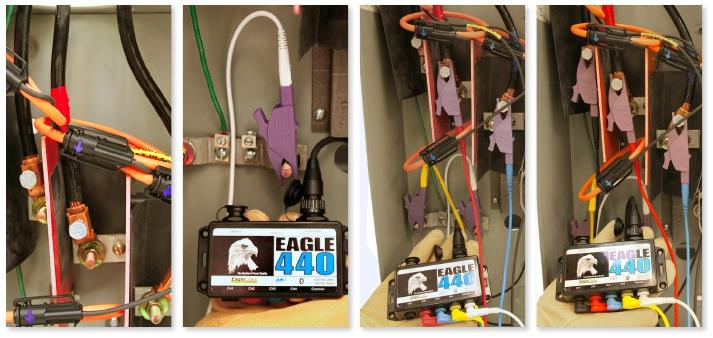
photos-hooking-up-the-eagle-440

  1. Wrap the CTs around the conductors with the arrows facing towards the load. Then connect the CT cable to the recorder.
  2. Connect the common (White) voltage lead to the recorder; and connect the voltage clip to the according to your circuit type.
  3. Connect the voltage leads for channels 4 (Yellow), 3 (Blue), and 2 (Red) to the recorder; then connect the voltage clips to clip the indicated Channel 2, 3, and 4 conductors.
  4. Connect the channel 1 (Black) voltage lead to the recorder; then use the dolphin or alligator to attach it to the correct conductor.


Note: It is important to connect the channel 1 voltage lead last, since this will start the two-minute countdown for recording. The LED on the side of the recorder will blink every other second during the two-minute countdown. Once the two-minute countdown is completed, recording begins and the status LED will blink once every six seconds.

Have a PQ question? Ask Merlin™ — free. Send it to askmerlin@powermonitors.com or text (540) 383-3144.

Power Monitors, Inc. — Tools you Need. People you Trust.

Power Monitors, Inc. is an industry-leading product design and manufacturing firm based in Mt. Crawford, Virginia. PMI® strives to solve power quality problems by listening to our customers and working with them to design and manufacture products. Total customer satisfaction is the primary goal of all PMI® staff.

24/7 Tech Support 800.296.4120

Resources

  • White Papers
  • Videos
  • Training
  • Live Webinars
  • PQ Resources
  • Support

Company

  • About Us
  • Contact
  • Careers
  • Newsletter
  • Product Registration
  • Terms & Conditions
800 N Main St, Mt Crawford, VA 22841 | Toll Free 800.296.4120 | Fax 540.432.9430
© 2026 Power Monitors, Inc.